Поделиться


1

2
|
93. |
CHARACTERISTIC FEATURES OF MORPHOLOGICAL CHANGES IN THE SPLEEN TISSUE OF WHITE RATS AFTER A MODERATE TRAUMATIC BRAIN INJURY
Fayziev Хurshid Burhanovich |
615-620 |
10.5958/2278-4853.2021.00739.4 |
|
94. |
INSPECTION OF CONCRETE IN REINFORCED CONCRETE ELEMENTS
Ugiloy Abdukhalimjohnovna Mirzaakhmedova |
621-628 |
10.5958/2278-4853.2021.00734.5 |
|
95. |
METHODOLOGY FOR ASSESSING THE ECONOMIC EFFICIENCY OF INNOVATION ACTIVITIES
Tarakhtieva Gulmira Kulbaevna |
629-637 |
10.5958/2278-4853.2021.00740.0 |
|
96. |
DIGITALIZATION - OPPORTUNITY FOR MANAGEMENT DEVELOPMENT IN AN INDUSTRIAL FACTORY
Mirsaidova Shaxnoza Areslonbekovna |
638-642 |
10.5958/2278-4853.2021.00722.9 |
|
97. |
A STUD OF INFLUENCE OF SOWING TIME, SEED AND MINERAL FERTILIZER RATES ON TRITICALE “SARDOR” VARIETY PRODUCTIVITY INDICATORS
Bakhtiyor Sadullaevich Kushmatov, Bakhodir Meylikovich Kholikov |
643-648 |
10.5958/2278-4853.2021.00752.7 |
|
98. |
IMPROVING THE EFFECTIVENESS OF CONTINUING MUSIC EDUCATION THROUGH TECHNOLOGICAL DESIGN
Charos Nematovna Torayeva |
649-652 |
10.5958/2278-4853.2021.00753.9 |
|
99. |
THE IMPORTANCE OF THEMATIC CONCERTS IN THE EFFECTIVENESS OF EDUCATION
Kholbekov M |
653-656 |
10.5958/2278-4853.2021.00754.0 |
|
100. |
DESCRIPTION OF THE HUMAN SPIRIT IN COMPARATIVE PHRASEOLOGICAL UNITS
Laylo Buriboyevna Dolieva |
657-660 |
10.5958/2278-4853.2021.00751.5 |
|
101. |
COMPARATIVE ANALYSIS OF THE DEVELOPMENT CHARACTERISTICS OF THE TOURISM INDUSTRY IN ECONOMIC DEVELOPED AND DEVELOPING COUNTRIES
Nazira Tokhtaevna Azizova, Zuhra Shuhratilloevna Norova |
661-669 |
10.5958/2278-4853.2021.00750.3 |
|
102. |
DIRECTIONS FOR THE DEVELOPMENT OF INTERNATIONAL TOURISM
Nazira Tokhtaevna Azizova, Zilola Akramkulovna Rasulkulova |
670-676 |
10.5958/2278-4853.2021.00749.7 |
13
|
|
|
|
DOI:10.5958/2278-4853.2021.00734.5
INSPECTION OF CONCRETE IN REINFORCED CONCRETE
ELEMENTS
Ugiloy Abdukhalimjohnovna Mirzaakhmedova*
*Senior Teacher,
Department of Construction of Buildings and Structures, Faculty of Construction,
Fergana Polytechnic Institute,
Fergana city, UZBEKISTAN
Email id: mirzaahmedova@fer.uz
![]()
Investigation of some characteristic values of concrete in reinforced concrete elements is necessary. This survey makes it possible to assess the actual work of concrete in the design of reinforced concrete. It is recommended to measure the width of crack opening in reinforced concrete elements in the places of maximum opening and at the level of stretched reinforcement. The length of the cracks is measured using a millimeter ruler, and the width of the opening is measured with a template thickness gauge, graduated loupes with 4x magnification or measuring microscopes with 24 x magnifications.
KEYWORDS: reinforced concrete structures, cracks, preliminary examination, accuracy, concrete strength, method of determination, testing, hidden defects, reinforcement, degree of corrosion.
![]()
It is recommended to measure the width of crack opening in reinforced concrete elements in the places of maximum opening and at the level of stretched reinforcement. The length of the cracks is measured using a millimeter ruler, and the width of the opening is measured with a template thickness gauge, graduated loupes with 4x magnification or measuring microscopes with 24 x magnifications. To improve the reading accuracy, it is advisable to install a 100 mm long tube between the object and the microscope eyepiece [1-12].
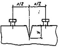
The depth of cracks can be determined using needles and thin wire rods, the ultrasonic pulse method, and also by the formula:
Where: V - thespeedofultrasoundinundisturbedconcrete; t and t1 - thepropagationtimeoftheultrasonicsignalonthebase, respectively, X sm in the area without cracks and with a crack (Fig. 1)
For cases when it is difficult to directly measure the width of the force crack opening at the level of the reinforcement of bending elements acrcz it is allowed to calculate it by the formula:
amax
Where: acrcmax - thewidthofthecrackonthesurfaceatthepointofmaximumopening; h - element height;hd - the thickness of the concrete cover.
To observe the dynamics of the development of cracks in reinforced concrete elements in time, in addition to the well-known "beacons", various kinds of devices are used, in particular, slot gauges, fixed with dowels.
The strength of concrete should, as at the stage of preliminary surveys, be determined in those places where, according to the structure's operation scheme, it is of the greatest importance from the point of view of the bearing capacity, as well as in the protective layer of the preserved structures..[1-14]
To determine the strength, instruments and devices of mechanical action and acoustic devices are used.
The accuracy and reliability of surface methods for determining the strength of concrete increases significantly when completing, when a correlation is observed between indirect indicators.When the methods of elastic rebound and plastic deformation are combined, the concrete strength R is determined by the:
Where: ris - radiusofthesphericalimprint; mb - themassofthestriker; - constant of the device; hj - the height of the elastic rebound; di - the diameter of the plastic imprint.
Acoustic tests of concrete strength are performed using instruments. At the same time, along with the strength, the homogeneity of concrete in terms of density, the presence of voids, hidden defects, and the depth of cracks are assessed.
It is allowed to use various modifications of ultrasonic devices to improve the accuracy and reliability of their operation.
Of the partially destructive methods for determining the strength of concrete, which do not affect the serviceability of structures, the method of extracting samples (cores, cubes) from relatively massive elements with subsequent testing of samples, the method of shearing the rib of the structure and the method of shearing off with shearing are used. The latter gives the most reliable results (with preserved smooth surfaces of the element and concrete strength of more than 8 MPa). This method is recommended to be used as a basic method in all cases when it is difficult to extract a sufficient number of cores or samples of the correct shape for testing by destructive methods, and the above non-destructive mechanical and acoustic methods are used in conjunction with the basic one.
After testing the strength of concrete by the method of separation with spalling, a visual inspection of the fresh fracture of the concrete is carried out, while fixing:
- Type and maximum size of coarse aggregate grains;
- Approximate ratio in percentage between large aggregate and mortar part;
- The presence of cracks and other defects in the mortar part, coarse aggregate or at the contact between them;
- The nature of concrete tearing (for coarse aggregate, contact between the coarse aggregate and the mortar part, mixed);
- Presence of ash and salt crystals in concrete pores;
- The depth of neutralization of concrete by phenolphthalein test.
If it is possible to extract at least a small amount of cores from the inspected structures (3-5), it is recommended to evaluate the strength of concrete by ultrasonic testing.
Having measured the speed of propagation of ultrasound in several areas of the examined structures, cores are extracted from those places where the speed of propagation of ultrasonic waves is greatest. Having then determined the strength of concrete in cores and taking it as a standard (reference sample), the strength of concrete R in other areas according to ultrasonic test data is calculated by the formula:
RRsup(1V /Vsup)/(1 7,87V /Vsup) (4)
Where: Rsup- thestrengthoftheconcreteofthereferencesample (core);V - - the difference between the velocities of propagation of ultrasonic waves in the reference sampleVsup and at the measured point.
Sample preparation and mechanical tests of cores are carried out in accordance with the Recommendations for assessing the quality of concrete in hydraulic structures using cores.
Testing the strength of concrete by various methods is performed as follows. The location for joint tests is selected by the basic and indirect, for example, the ultrasonic method (calibration tests). To do this, first, concrete tests are performed in several areas by an indirect method. Areas where the coefficient of uniformity of concrete strength (the ratio of the standard deviation of concrete strength to average strength) is the smallest are recognized as suitable for carrying out calibration tests. In all cases, he should not be St. 25%.
Tests are carried out using basic and ultrasonic methods. The number of tests should not be less than 10.
To assess the results of calibration tests, the significance of the difference in the average strength values determined by the basic and indirect methods is compared. Todothis, determinethevalue:
U
2![]() Rbb Rtnd
Rbb Rtnd ![]() /bb
tnd
(5)
/bb
tnd
(5)
Where: ![]() Rbb Rtnd
Rbb Rtnd ![]() -themodulusofthedifferencebetweentheaveragevalues
ofstrength, determinedbythebasicandindirectmethods; bb,tnd - range (the
difference between the largest and the smallest values for the basic and
indirect methods).
-themodulusofthedifferencebetweentheaveragevalues
ofstrength, determinedbythebasicandindirectmethods; bb,tnd - range (the
difference between the largest and the smallest values for the basic and
indirect methods).
If the value U Ut (Table 1), then the difference in the value of the average strengths is considered insignificant, and the methods for determining the strength are compatible; TABLE 1.
If the indirect method is found to be suitable, the correlation coefficient is calculated between the strength values determined by the basic and indirect methods. Then the concrete strength is determined by an indirect method on the entire volume of the examined structures. The number of measurements - at least 30 in each of the selected zones, depending on the state of the element and operating conditions. In this case, the total volume of tests by the indirect method in each zone is taken as the volume of the controlled batch, and the volume of tests by the basic method is taken as the sample size.
The value of the cube compressive strength of concrete according to the test results for each of the selected zones is determined as the weighted average for each of the methods with weight Pbb and Pind :
R ![]() Rbb nSindind2 Sn2bbSRind2indnSbbbb2 nind
(6)
Rbb nSindind2 Sn2bbSRind2indnSbbbb2 nind
(6)
bb
Where:Sind2 ,Sbb2 - variance of indirect and base methods;
n 2
![]() Sbb2 Ri R /n1
(7)
Sbb2 Ri R /n1
(7)
i1
![]() Where:
n - numberofbaselinestrengthdeterminations; R - average value of
strength when measured; Ri - the results of a single (i-th)
determination of strength. Thevalueis Sind2 determinedinthesame.
Where:
n - numberofbaselinestrengthdeterminations; R - average value of
strength when measured; Ri - the results of a single (i-th)
determination of strength. Thevalueis Sind2 determinedinthesame.
In cases where the difference between the concrete strength indicators, determined by the shearoff method and the indirect method, is greater than permissible according to the formula, the values of the concrete strength in the area where the non-destructive testing was carried out are determined by the formula:
where: R - concretestrength; Rind -concrete strength, determined by ultrasonic method;ki - the coefficient of coincidence, determined by the formula:
n m
ki mRbb /nRind (9)
1 1
To check the actual reinforcement and the thickness of the protective layer of concrete, use magnetic methods or methods of transillumination and ionizing radiation with a control check of the results obtained. It is carried out by punching furrows and direct measurements. Of the domestic devices, usually used are meters of the protective layer of the IZS type, in particular IZS-10N, TU 25-06.18-85.79. The measurement range of the protective layer thickness is 5-30 mm with a reinforcement diameter of 4-10 mm and 10-50 mm - at 12-32 mm.
When the distance between the reinforcement rods is less than 60 mm, the use of IZS-type devices is.
Theassignment of non-stressed bar reinforcement to one class or another is preliminarily carried out in appearance: smooth reinforcement - class A-I, reinforcement of periodic profile with protrusions along a helical line - A-II; with herringbone protrusions - А-III and higher; smooth flattened in two mutually perpendicular directions - St3, hardened by cold flattening. Another profile of the rods indicates the use of foreign-made reinforcement. In this case, the class of reinforcement is set according to foreign standards. If the design of the bar is difficult to determine due to significant surface corrosion, it is recommended to open the reinforcement in an area with less pronounced corrosion.
In the process of examinations, the depth of the neutralized concrete layer is determined by a colorimetric method based on the change in the color of organic indicators depending on the pH value. The assessment is carried out by treating a fresh concrete chip with pH indicators. 1% alcoholic solution of phenolphthalein changes color from colorless (pH = 9.3) to crimson (pH = 10.5); 0.1% aqueous solution of alizarin red - from yellow (pH = 10.1) to lemon (pH = 12.1).
A minute after the application of the indicator solution, measure the depth of concrete neutralization with a ruler with an accuracy of 1 mm.
The depth of penetration of chlorine ions is determined by wetting a fresh fracture of concrete with a 1% solution of silver nitrate. Turbidity of the solution indicates the presence of chlorine ions in the concrete (more than 0.3% of the mass of cement).
The depth of destruction of concrete under the influence of liquid acidic media is determined by removing the corroded layer with a sharp tool.
The degree of corrosion of the reinforcement is assessed by the nature of the corrosion products (solid, pitting, spots, thin coating, layered, color and density), the area of surface damage (as a percentage of the total exposed surface) and the depth of corrosion damage. The latter is determined with relatively uniform corrosion by the difference (average) of the design and actual diameters of the reinforcement, divided by 2; in case of pitting corrosion, the depth of the ulcers is measured with an indicator needle. If the surface of the shaft is lined with a large number of ulcers, the initial position of the indicator hand can be set using a calibrated plate (such as a safety razor blade) placed on the sample surface.
For a quantitative assessment of the size of corrosion of the reinforcement, the reinforcement is opened in 10 structures of the same type, at least in the most corroded sections with a length of 1 m.At each of such sections, the retained diameter of the reinforcement is measured in three places after removing the corrosion products of steel mechanically, for example, using an emery wheel, until a smooth, shiny steel surface is obtained.
Opening of prestressed reinforcement (outside the anchorage zone) can be allowed if the operational loads have extinguished or significantly weakened the concrete compression forces created by prestressing, which, in particular, may be evidenced by the appearance of transverse cracks in the area of the prestressed reinforcement or element deflection. and also after the implementation of the appropriate safety measures.
UKB-1m device: Measures the speed of propagation of an acoustic pulse, the change in its energy and frequency-amplitude spectrum. The accuracy of measuring the amplitude of the pulses depends on the reliability of the acoustic contacts of the probes of the device and concrete, therefore, along with the attenuation coefficient, the nature of the reverberation process in the section of the element is also determined. When inspecting massive reinforced concrete structures at low frequencies (20-150 kHz), the sensitivity of the devices is low. However, some specific defects and damage caused by poor-quality concrete placement, exposure to high and low temperatures, corrosion, are easily detected.
The areas of the damaged layer are shown by the fracture of the longitudinal hodograph line (Fig. 2). The thickness of the modified surface layer is found by the formula:
Where: la - isthedistancefromtheemittingtransducertothebreakpointofthehodograph; V1 and V2 - respectively,the speed of ultrasound in undamaged and damaged concrete layers.
Cracks, cavities, areas of weakened concrete, as well as the thickness of the protective layer, the size and location of reinforcement in structures can be identified using radiation flaw detection. When using special methods of registration of radiation, it is possible to determine the particle size distribution and the content of individual fractions of the aggregate. X-ray devices, gamma devices with radioactive sources and electron accelerators (betatrons), which emit bremsstrahlung radiation, are used to transilluminate reinforced concrete elements. The maximum thickness of structures available for radiation flaw detection is 200-250 mm for X-ray machines, 300-500 mm for radioactive radiation sources, and 2 m for betatrons..[1-14]
When translucent structures with a thickness of 0.2-1 m can be detected reinforcement with a diameter of 3 mm or more. Shells and voids are found when their size is equal to 3-5% of the thickness of the element. Cracks are fixed if they do not deviate from the direction of transmission by an angle of more than 5-7%.
The density of concrete in structures is determined using radiometric densitometers of various types by direct (through) transmission or diffuse measurement. The first method mv is used with a structure thickness of up to 50 cm and free access to opposite sides of the structure. In the first method, it is determined by the weakening of the flow - rays passing through the concrete, in the second - by the scattering of γ-radiation. The moisture content of the tested concrete should not differ from the moisture content of concrete, according to the tests of which the device was calibrated by more than + 5%.
The number of measurements should be at least two per 1 m2 of area and at least eight per structure.
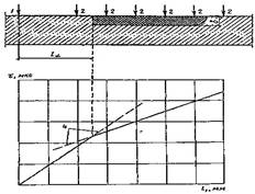
1, 2 - installation zones of the emitter and receiver; 3 - area of damaged concrete structure; 4 - fracture of the hodograph line in the area of damaged concrete
On the basis of concrete tests by ultrasonic and radioisotope methods, the dimensions and depth of defects and damages, in particular cracks, are specified, and, if necessary, additional control clearing is carried out.
These data are given in the conclusion about the tests carried out and are used in the analysis of the results of determining the strength of concrete by various methods. They are also taken into account when choosing places for sampling concrete for laboratory research.
REFERENCES:
1. Roitman A. "Repair and modernization of a building and structure" M. Higher School 1997.
2. Abdukhalimjohnovna M. U. Technology of Elimination Damage and Deformation in Construction Structures //The American Journal of Applied sciences. – 2021. – Т. 3. – №. 5. – С. 224-228.
3. Abdukhalimjohnovna M. U. Failure Mechanism of Bending Reinforced Concrete Elements under The Action Of Transverse Forces //The American Journal of Applied sciences. – 2020. – Т. 2. – №. 12. – С. 36-43.
4. Mirzaakhmedov A. T., Mirzaakhmedova U. A. Prestressed losses from shrinkage and nonlinear creep of concrete of reinforced concrete rod systems //EPRA International journal of research and development (IJRD). – 2020. – Т. 5. – №. 5. – С. 588-593.
5. Mirzaahmedov, A. T. (2020). Algorithm for Calculation of Multi Span Uncut Beams Taking Into Account the Nonlinear Work Of Reinforced
Concrete. TheAmericanJournalofAppliedsciences, 2(12), 26-35.
6. Мирзаахмедов А. Т., Мирзаахмедова У. А. Алгоритм расчета железобетонных балок прямоугольного сечения с односторонней сжатой полкой //Проблемы современной науки и образования. – 2019. – №. 12-2 (145).
7. Mamazhonovich M. Y., Mirzaakbarovna M. S. To Calculation Of Bended Elements Working Under The Conditions Of Exposure To High And High Temperatures On The Lateral Force By A New Method //The American Journal of Applied sciences. – 2021. – Т. 3. – №. 5. – С. 210-218.
8. Mahkamov Y. M., Mirzababaeva S. M. Strength of bending reinforced concrete elements under action of transverse forces under influence of high temperatures //ACADEMICIA: An International Multidisciplinary Research Journal. – 2020. – Т. 10. – №. 5. – С. 618-624.
9. Mahkamov Y. M., Mirzababaeva S. M. Strength of bending reinforced concrete elements under action of transverse forces under influence of high temperatures //ACADEMICIA: An International Multidisciplinary Research Journal. – 2020. – Т. 10. – №. 5. – С. 618-624.
10. Asrorovna A. Z. Effects Of A Dry Hot Climate And Salt Aggression On The Permeability Of Concrete //The American Journal of Engineering and Technology. – 2021. – Т. 3. – №. 06. – С. 6-10.
11. Abobakirova Z. A. Regulation of the Resistance of Cement Concrete with Polymer Additive and Activated Liquid Medium //The American Journal of Applied sciences. – 2021. – Т. 3. – №. 04. – С. 172-177.
12. Goncharova N. I., Abobakirova Z. A., Mukhamedzanov A. R. Capillary permeability of concrete in salt media in dry hot climate //AIP Conference Proceedings. – AIP Publishing LLC, 2020. – Т. 2281.
– №. 1. – С. 020028.
13. Akhrarovich A. X., Mamajonovich M. Y., Abdugofurovich U. S. Development Of Deformations In The Reinforcement Of Beams With Composite Reinforcement //The American Journal of Applied sciences. – 2021. – Т. 3. – №. 5. – С. 196-202.
14. Кимсанов З. О., Гончарова Н. И., Абобакирова З. А. Изучение технологических факторов магнитной активации цементного теста //Молодой ученый. – 2019. – №. 23. – С. 105-106.

732

733
Материалы на данной страницы взяты из открытых источников либо размещены пользователем в соответствии с договором-офертой сайта. Вы можете сообщить о нарушении.