Поделиться

Theoretical material for the lesson, definitions for concepts
Faraday's law of induction (briefly, Faraday's law) is a basic law of electromagnetism predicting how a magnetic field will interact with an electric circuitto produce an electromotive force (EMF)—a phenomenon called electromagnetic induction. It is the fundamental operating principle of transformers, inductors, and many types of electrical motors, generators and solenoids.
The definition of surface integral relies on splitting the surface Σ into small surface elements. Each element is associated with a vector dA of magnitude equal to the area of the element and with direction normal to the element and pointing "outward" (with respect to the orientation of the surface). For a loop of wire in a magnetic field, the magnetic flux ΦB is defined for any surface Σ whose boundary is the given loop. Since the wire loop may be moving, we write Σ(t) for the surface. The magnetic flux is the surface integral:
![]()
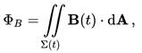
where dA is an element of surface area of the moving surface Σ(t), B is the magnetic field, and B·dA is a vector dot product representing the element of flux through dA. In more visual terms, the magnetic flux through the wire loop is proportional to the number of magnetic flux lines that pass through the loop.
When the flux changes—because B changes, or because the wire loop is moved or deformed, or both—Faraday's law of induction says that the wire loop acquires an EMF, E, defined as the energy available from a unit charge that has travelled once around the wire loop.[15][16][17] (Note that different textbooks may give different definitions. The set of equations used throughout the text was chosen to be compatible with the special relativity theory.) Equivalently, it is the voltage that would be measured by cutting the wire to create an open circuit, and attaching a voltmeter to the leads.
Faraday's law states that the EMF is also given by the rate of change of the magnetic flux:
![]()
![]()
where ![]() is the electromotive force (EMF)
and ΦB is the magnetic
flux.
is the electromotive force (EMF)
and ΦB is the magnetic
flux.
The direction of the electromotive force is given by Lenz's law.
The laws of induction of electric currents in mathematical form was established by Franz Ernst Neumann in 1845.
Faraday's law contains the information about the relationships between both the magnitudes and the directions of its variables. However, the relationships between the directions are not explicit; they are hidden in the mathematical formula.
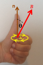
A Left Hand Rule for Faraday's Law. The sign of ΔΦB, the change in flux, is found based on the relationship between the magnetic field B, the area of the loop A, and the normal n to that area, as represented by the fingers of the left hand. If ΔΦB is positive, the direction of the EMF is the same as that of the curved fingers (yellow arrowheads). If ΔΦB is negative, the direction of the EMF is against the arrowheads.
It is possible to find out the direction of the electromotive force (EMF) directly from Faraday’s law, without invoking Lenz's law. A left hand rule helps doing that, as follows:
· Align the curved fingers of the left hand with the loop (yellow line).
· Stretch your thumb. The stretched thumb indicates the direction of n (brown), the normal to the area enclosed by the loop.
· Find the sign of ΔΦB, the change in flux. Determine the initial and final fluxes (whose difference is ΔΦB) with respect to the normal n, as indicated by the stretched thumb.
· If the change in flux, ΔΦB, is positive, the curved fingers show the direction of the electromotive force (yellow arrowheads).
· If ΔΦB is negative, the direction of the electromotive force is opposite to the direction of the curved fingers (opposite to the yellow arrowheads).
For a tightly wound coil of wire, composed of N identical turns, each with the same ΦB, Faraday's law of induction states that[21][22]
![]()
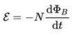
where N is the number of turns of wire and ΦB is the magnetic flux through a single loop.
Additional guidelines for organizing a lesson
Lesson starts with introducesing the topic of day and spells out the learning outcomes they will possess after the study. Acquaint students with the following issues:
• The theme of the lesson
• The objectives of the lesson
• The criteria of success for the lesson
• The plan of events for the lesson
• Pre-teach the subject specific vocabulary.
Learners will share their experiences with electromagnetic induction.
Then students can deduce topic of the lessen and objectives, for clarification you can show topic and the learning objectives on the presentation.
Then Subject-specific vocabulary & terminology will be presented to the students and their activities during the research work will be explained.
Then teacher will ask learners to investigate the effects of moving a bar magnet into and out of a coil connected to a sensitive centre-zero galvanometer. After that would discuss the results with the class and draw out the key points:
-There is an induced voltage in the (secondary) coil when the flux linkage changes.
-If a wire is moved parallel to the field lines there is no induced voltage.
-The size of the induced voltage depends on the rate of change of flux-linkage. (more obvious with the first experiment)
-Induced current in a closed circuit counterwork the changes of a magnetic flux caused by this current.
Then teacher will explain Lenz’s law by using a magnet falling slowly in a copper tube by the existence of a magnetic field with opposite direction. Would give questions on a worksheet.
Learners demonstrate and explain Lenz’s law by using a magnet falling slowly in a copper tube by the existence of a magnetic field with opposite direction.
• Watch videos on electromagnetic induction
• Summarize their observations and conclusions findings.
• Answers questions about the videos.
• Attempt questions on the worksheet
Simulation of the ‘Faraday’s law’:
http://phet.colorado.edu/en/simulation/legacy/faraday
or
Simulation of the ‘Faraday’s law 2’:
http://phet.colorado.edu/en/simulation/faradays-law
The Faraday’s law by BBC:
http://www.bbc.co.uk/schools/gcsebitesize/science/add_ocr_pre_2011/electric_circuits/mainsproducedrev1.shtml
Lentz rule:
https://www.youtube.com/watch?v=M2e0JbIym-I&list=PLJ8TtQgi6QOqW-VQ0vB0XbzHz9_S8bh90&index=3
Lentz rule (experiment):
https://www.youtube.com/watch?v=q-Rd2DvlTU4
E.m.f induction in moving conductors:
https://www.youtube.com/watch?v=vGD4LWmAUv4&index=5&list=PLJ8TtQgi6QOqW-VQ0vB0XbzHz9_kS8bh90
Then teacher Highlight key concepts, definitions, and equations learnt using the concept map, ask students to do questions on the worksheet provided, look forward to the next lesson.
During this time students attempt the questions given by the teacher, summarize the main concepts, definitions, and equations learnt, reflect on their own learning, evaluate their own work and the work of their classmates. Teacher will give homework complete the specified thinking tasks for this lesson.
Additional multilevel (on differentiation) tasks
The teacher assigns questions 1- 5 to weak students, questions 6- 15 to the average students, questions 16 - 18 to the strong students
Recommendations for formative assessment
Students think of everything they already know about the importance of electricity for our life, and record this information in the first column of the table given.
Students discuss learning objectives and success criteria.
Students work in groups. Each group fill out one line of the table provided by the teacher.
Students share their knowledge with neighboring pairs, filling in the table. Students make a list of electric charge properties significant for our daily life.
Answers, criteria for assignments, additional materials for the lesson
Induced EMF and Induced Current
Motional EMF
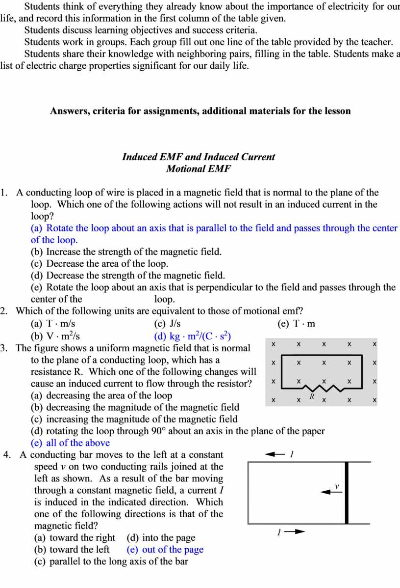
1. A conducting loop of wire is placed in a magnetic field that is normal to the plane of the loop. Which one of the following actions will not result in an induced current in the loop?
(a) Rotate the loop about an axis that is parallel to the field and passes through the center of the loop.
(b) Increase the strength of the magnetic field.
(c) Decrease the area of the loop.
(d) Decrease the strength of the magnetic field.
(e) Rotate the loop about an axis that is perpendicular to the field and passes through the center of the loop.
2. Which of the following units are equivalent to those of motional emf?
(a) T × m/s (c) J/s (e) T × m
(b) V × m2/s (d) kg × m2/(C × s2)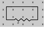
3. The figure shows a uniform magnetic field that is normal to the plane of a conducting loop, which has a resistance R. Which one of the following changes will cause an induced current to flow through the resistor?
(a) decreasing the area of the loop
(b) decreasing the magnitude of the magnetic field
(c) increasing the magnitude of the magnetic field
(d) rotating the loop through 90° about an axis in the plane of the paper
(e) all of the above
|
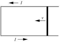
4. A conducting bar moves to the left at a constant speed v on two conducting rails joined at the left as shown. As a result of the bar moving through a constant magnetic field, a current I is induced in the indicated direction. Which one of the following directions is that of the magnetic field? (a) toward the right (d) into the page (b) toward the left (e) out of the page (c) parallel to the long axis of the bar |
|
|
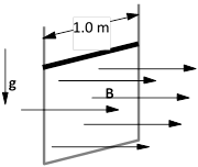
5. A 2.0-kg rod that has a length of 1.0 m and a resistance of 4.0 slides with constant speed down a pair of frictionless vertical conducting rails that are joined at the bottom. Other than the rod, the rest of the circuit is resistanceless. A uniform magnetic field of magnitude 3.0 T is perpendicular to the plane formed by the rod and the rails as shown. Determine the speed of the rod. (a) 0.38 m/s (d) 5.6 m/s (b) 0.90 m/s (e) 8.7 m/s (c) 2.6 m/s |
|
6. A 0.45-m metal rod moves 0.11 m in a direction that is perpendicular to a 0.80-T magnetic field in an elapsed time of 0.036 s. Assuming that the acceleration of the rod is zero m/s2, determine the emf that exists between the ends of the rod.
(a) 1.1 V (d) 9.1 ´ 10–5 V
(b) 0.27 V (e) This cannot be determined without knowing the
(c) 0.076 V orientation of the rod relative to the magnetic field.
Magnetic Flux
7. A 0.50-T magnetic field is directed perpendicular to the plane of a circular loop of radius 0.25 m. What is the magnitude of the magnetic flux through the loop?
(a) 0.049 Wb (c) 0.20 Wb (e) zero Wb
(b) 0.098 Wb (d) 0.39 Wb
8. The Earth’s magnetic field passes through a square tabletop with a magnitude of 4.95 ´ 10-5 T and is directed at an angle of 165° relative to the normal of the tabletop. If the tabletop has 1.50-m sides, what is the magnitude of the magnetic flux through it?
(a) 1.08 ´ 10–4 Wb (c) 2.88 ´ 10–5 Wb (e) 3.30 ´ 10–6 Wb
(b) 7.11 ´ 10–5 Wb (d) 1.92 ´ 10–5 Wb
9. A circular copper loop is placed perpendicular to a uniform magnetic field of 0.50 T. Due to external forces, the area of the loop decreases at a rate of 1.26 10–3 m2/s. Determine the induced emf in the loop.
(a) 3.1 ´ 10–4 V (c) 1.2 ´ 10–3 V (e) 3.1 V
(b) 6.3 ´ 10–4 V (d) 7.9 ´ 10–3 V
10. A conducting loop has an area of 0.065 m2 and is positioned such that a uniform magnetic field is perpendicular to the plane of the loop. When the magnitude of the magnetic field decreases to 0.30 T in 0.087 s, the average induced emf in the loop is 1.2 V. What is the initial value of the magnetic field?
(a) 0.42 T (c) 0.87 T (e) 1.9 T
(b) 0.75 T (d) 1.2 T
11. A uniform magnetic field passes through two areas, A1 and A2. The angles between the magnetic field and the normals of areas A1 and A2 are 30.0° and 60.0°, respectively. If the magnetic flux through the two areas is the same, what is the ratio A1/A2?
(a) 0.577 (c) 1.00 (e) 1.73
(b) 0.816 (d) 1.23
12. A 150-turn solenoid carries a current of 12 A. The radius of the solenoid is 0.050 m; and its length is 0.18 m. Determine the magnetic flux through the circular cross-sectional area at the center of the solenoid.
(a) 1.8 ´ 10–5 Wb (c) 4.3 ´ 10–4 Wb (e) 2.2 ´ 10–3 Wb
(b) 9.9 ´ 10–5 Wb (d) 7.0 ´ 10–4 Wb
Faraday’s Law of Electromagnetic Induction
13. A magnetic field is directed perpendicular to the plane of a 0.15-m ´ 0.30-m rectangular coil consisting of 120 loops of wire. To induce an average emf of -1.2 V in the coil, the magnetic field is increased from 0.1 T to 1.5 T during a time interval t. Determine t.
(a) 0.053 s (c) 1.6 s (e) 7.6 s
(b) 0.13 s (d) 6.3 s
14. The area of a 333-turn conducting coil is 7.85 ´ 10–3 m2. The resistance of the coil is 10.4 . If the coil is oriented as shown in a magnetic field B, at what rate in T/s should the magnitude of B change to induce a current of 2.50 ´ 10–3 A in the coil?
(a) 0.0155 T/s (c) 0.228 T/s (e) 1.52 T/s
(b) 0.0996 T/s (d) 0.757 T/s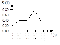
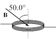
15. A circular coil of wire has 25 turns and has a radius of 0.075 m. The coil is located in a variable magnetic field whose behavior is shown on the graph. At all times, the magnetic field is directed at an angle of 75° relative to the normal to the plane of a loop. What is the average emf induced in the coil in the time interval from t = 5.00 s to 7.50 s?
(a) -18 mV (d) -140 mV
(b) -49 mV (e) -180 mV
(c) -92 mV
Questions 16 through 19 pertain to the situation described below:
|
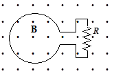
The figure shows a uniform, 3.0-T magnetic field that is normal to the plane of a conducting, circular loop with a resistance of 1.5 and a radius of 0.024 m. The magnetic field is directed out of the paper as shown. Note: The area of the non-circular portion of the wire is considered negligible compared to that of the circular loop. |
|
16. What is the magnitude of the average induced emf in the loop if the magnitude of the magnetic field is doubled in 0.4 s?
(a) 0.43 V (c) 0.014 V (e) 0.038 V
(b) 0.65 V (d) 0.027 V
17. What is the average current around the loop if the magnitude of the magnetic field is doubled in 0.4 s?
(a) 2.8 * 10–3 A, clockwise (d) 9.0 * 10–3 A, clockwise
(b) 4.5 * 10–3 A, clockwise (e) 9.0 * 10–3 A, counterclockwise
(c) 4.5 * 10–3 A, counterclockwise
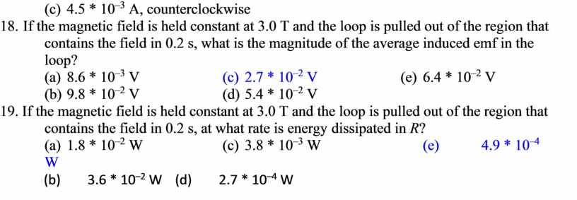
18. If the magnetic field is held constant at 3.0 T and the loop is pulled out of the region that contains the field in 0.2 s, what is the magnitude of the average induced emf in the loop?
(a) 8.6 * 10–3 V (c) 2.7 * 10–2 V (e) 6.4 * 10–2 V
(b) 9.8 * 10–2 V (d) 5.4 * 10–2 V
19. If the magnetic field is held constant at 3.0 T and the loop is pulled out of the region that contains the field in 0.2 s, at what rate is energy dissipated in R?
(a) 1.8 * 10–2 W (c) 3.8 * 10–3 W (e) 4.9 * 10–4 W
(b) 3.6 * 10–2 W (d) 2.7 * 10–4 W
Скачано с www.znanio.ru


Материалы на данной страницы взяты из открытых источников либо размещены пользователем в соответствии с договором-офертой сайта. Вы можете сообщить о нарушении.