Teacher Guides of the Lesson
Theoretical material for the lesson, definitions for concepts
Discussion and demonstration: Induction effects
The first two demonstrations involve
moving a wire in a magnetic field and then a permanent magnet into and out of a
small coil. In both it is important to emphasise that:
Ø ‘electricity’ is only produced while something is moving
Ø the faster the movement, the more ‘electricity’ we get
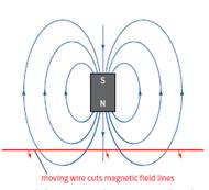
Cutting magnetic field lines
Start by thinking about a simple bar magnet. It has a magnetic field in the space around it. We represent this field by magnetic field lines. Now think about what happens when a wire is moved into the magnetic field (Figure). As it moves, it cuts across the magnetic field. Remove the wire from the field, and again it must cut across the field lines, but in the opposite direction. We think of this cutting of a magnetic field by a conductor as the effect that gives rise to an induced current in the conductor. It doesn’t matter whether the conductor is moved through the field or the magnet is moved past the conductor, the result is the same – there will be an induced current.

For a coil of N turns, the effect is N times greater than for a single turn of wire.
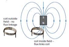
When the coil is outside the field, there are no magnetic field lines linking the coil.
When it is inside the field, field lines link the coil. Moving the coil into or out of the field changes this linkage, and this induces an e.m.f. across the ends of the coil.

Magnetic flux and magnetic flux linkage
Magnetic flux density B is defined by the equation
B = F/IL
Now we can go on to define magnetic flux as a quantity.
We picture magnetic flux density B as the number of magnetic field lines passing through a region per unit area.
Similarly, we can picture magnetic flux as the total number of magnetic field lines passing through an area A. For a magnetic field normal to A, the magnetic flux Φ must therefore be equal to the product of magnetic flux density and the area A.

a The magnetic flux is equal to BA when the field
is normal to the area.
b The magnetic flux becomes Bacosθ when the field is at an angle θ to the normal of the area.
The magnetic flux Φ through area A is defined as:
Φ = BA
where B is the component of the magnetic flux density perpendicular to the area.
How can we calculate the magnetic fl ux when B is not perpendicular to A?
When the field is parallel to the plane of the area, the magnetic flux through A is zero. To find the magnetic flux in general, we need to find the component of the magnetic flux density perpendicular to the area.
Magnetic flux = (B cos θ) × A
or simply:
Magnetic flux = BA cos θ
(Note that, when θ = 90°, flux = 0 and when θ = 0°,
flux = BA.)
For a coil with N turns, the magnetic flux linkage is defined as the product of the magnetic flux and the number of turns; that is:
Magnetic flux linkage = NΦ
or
Magnetic flux linkage = BAN cos θ
The unit for magnetic flux or flux linkage is the Weber (Wb).
One weber (1 Wb) is the flux that passes through an area of 1 m2 when the magnetic flux density is 1 T.
1 Wb = 1 T m2.
An e.m.f. is induced in a circuit whenever there is a change in the magnetic flux linking the circuit. Since magnetic flux is equal to BA cos θ, there are three ways an e.m.f. can be induced:
■■ changing the magnetic flux density B
■■ changing the area A of the circuit
■■ changing the angle θ.
Instructions for demonstrations and safety
Warning: experiments should be performed under the supervision of teachers or students follow the instructions of safety procedures.
Additional guidelines for organizing a lesson
1. Organization moment. Establishing emotional state. Checking for absent students.
2. Teacher introduces the topic and objectives of the lesson, assess criteria.
3. Teacher asks learners to do simple experiments involving a wire and coil of wire and a voltmeter. This will give them a chance to assess the knowledge that students bring to this section.
For this experiment, students at first try to predict what they will observe before they try the
experiment.
4. Students in pairs connect the coil of wire to the micro voltmeter and place it close to the magnet and note the effect on the meter as you do each of the following actions.
5. Teacher and learners discuss the results with the class and draw out the key points.
6. Teacher introduces the concept of magnetic flux as a flux of magnetic field lines penetrating this loop, and lead learners to the formula of magnetic flux Ф= BScosα. Introduce a unit of measuring magnetic flux 1 Wb=1T∙1 m2.
7. Teacher uses quantitative problem to calculate the flux linkage and flux density.
8. At the end of the lesson students are encouraged to reflect on what they have learned and
what they need to improve.
Recommendations for formative assessment
Activity1. Students discuss learning objectives and assess criteria.
Activity2. Learners do simple experiments involving a wire and coil of wire and a voltmeter.
This will give them a chance to assess the knowledge that students bring to this
section. For this experiment, students at first try to predict what they will observe
before they try the experiment.
Activity3. Students in pairs connect the coil of wire to the microvoltmeter and place it close to
the magnet and note the effect on the meter as you do each of the following actions.
Activity4. Learners discuss with a teacher the results with the class and draw out the key
points.
Activity5. Teacher introduces the concept of magnetic flux as a flux of magnetic field lines
penetrating this loop, and lead learners to the formula of magnetic flux Ф= BScosα.
Activity6. Whole class students calculate the flux linkage and flux density. Teacher invites
students to solve problem step by step at the blackboard.
Activity7. At the end of the lesson students are encouraged to reflect on what they have learned
and what they need to improve.
Answers, criteria for assignments, additional materials for the lesson
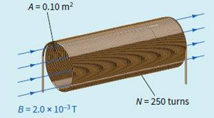
Figure shows a solenoid with a cross-sectional area 0.10 m2. It is linked by a magnetic field of flux density 2.0 ×10⁻³ T and has 250 turns. Calculate the
magnetic flux and flux linkage for this solenoid.
Step 1 We have B = 2.0 ×10⁻³ T, A = 0.10 m2, θ = 0°
and N = 250 turns. Hence we can calculate the flux Φ.
Φ = BA
Φ = 2 .0 × 10−3 × 0.10 = 2.0 × 10⁻⁴ Wb
Step 2 Now calculate the flux linkage.
magnetic flux linkage = NΦ
magnetic flux linkage = 2.0 ×10−4 × 250
= 5.0 × 10⁻² Wb

List of useful links and literature
Douglas C. Giancoli, Physics Principles with Applications, Seventh edition 2014.
Keith Johnson Physics for You IGCSE Updated Edition 2011
https://tap.iop.org/fields/electromagnetism/414/page_46948.html
David Sang, Graham Jones, Gurinder Chadha and Richard Woodside Cambridge International AS
and A Level Physics Coursebook
Скачано с www.znanio.ru
Материалы на данной страницы взяты из открытых источников либо размещены пользователем в соответствии с договором-офертой сайта. Вы можете сообщить о нарушении.