Поделиться

UDK 538.3
A NEW TYPE OF PROTECTIVE WEAPON BASED ON THE CREATION OF A ROTATING POWERFUL INTENSIVE BEAM OF ELECTROMAGNETIC WAVES (EMW) HIGH FREQUENCIES (HF).
Zhakatayev Toksan1. Doctor of Engineering Sc. Toksanzh@yandex.kz.
Kakimova Klara2. Master of Engineering Sc. K.kakimova@mail.ru.
1L. N. Gumilyov Eurasian National University.
Nur-Sultan, Kazakhstan.
2KarSTU, Karaganda, Kazakhstan.
Introduction.
All types of weapons used by humanity so far have the following great drawback. From the point of view of physics, it is necessary to allocate a very large amount of thermal energy in a very small period of time and in a very small limited volume. That is, they are all based on the explosive action of any charge, a source of ultra-high energy. This characteristic applies simultaneously: to a gunshot (powder) bullet, and to an atomic bomb, and to a missile with a nuclear warhead of various exposure radius. From the point of view of modern scientific knowledge and achievements, these types of weapons are outdated. They have relatively low efficiency and very high financial costs. From the point of view of modern new, universal human positions - a tank, mines and guns can be called a very terrible, ridiculous, stupid, cruel and deeply immoral creation of humanity. Which must be destroyed, removed from the circulation of human use as soon as possible, like all other types of killing and destroying weapons. And we will prove their futility later. Is it not possible to somehow try to evaluate what is wild fascism, cruel, not permissible barbarism - to kill people in such a way that pieces of metal plunge into a living human body? Tear a living man to pieces? These are unacceptable barbarism and savagery. Created by God, an incredibly mysterious, very complex, unrecognizable and at the same time marvelous world has unlimited possibilities to implement measures to protect the lives of people, in the presence of economic, political or military pressure from some strong country in relation to another weaker country.
There will be significant benefits for humanity if many weapons are melted down into metal. Then they will make cases for computers.
Advanced developed weapons must meet new requirements and principles. For example, to have a remote effect on a combat vehicle, missile or mechanism, as a result of which it will become non-radio controlled. In other words, it will simply turn into a pile of useless metal. It is also possible to influence people - on soldiers of the enemy army. When blocking radio communications - they will become vulnerable and useless. The maximum that they can do (with isolation of communication) is shoot in all directions from a machine gun until the cartridges end.
As a result of a protracted, "soft," continuous influence on the soldiers, they can be taken out of mental balance and rest. For example, if you continuously from somewhere from afar, from places not reached, affect their brains. Such weak effects can cause unpredictable diseases. After which the soldier himself will not want to fight, or will not be able to do so. The new principles of "soft weapons" are simple and humane: to bring the soldier to ill health, after which he will leave the zone of active hostilities.
This scientific paper describes a new type of protective weapon based on a very powerful intense rotating beam - electromagnetic wave beams (EMW) from installations above high frequencies (microwave) of continuous influence. Which are very far from the target.
Ultimately, we wish world peace and happiness to all mankind on earth. Since the new protective weapon we invented is just protecting, protecting peace, protecting the peace of ordinary and peaceful people throughout the earth. Who are sometimes defenseless to some aggressors and warlike people on the planet.
Theoretical solution.
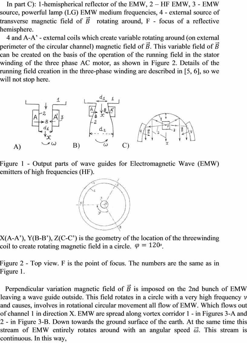
In near-Earth outer space, at some distance from the earth's surface (at a level above the ozone layer), the following simple equipment can be located, which continuously emits high frequency electromagnetic waves ( HF EMW) or above high frequencies (AHF EMW), microwave. The output portions, the output guides of which are shown in Figures 1. A, B are output parts designed for powerful magnetrons. The C-structure of output (radiating) part for EMW not above high frequency, not microwave. Various magnetrons can be used as sources of powerful microwave EMW [1-4]. In these sources they are described in sufficient detail, so let us not dwell on the description of their design and principle of operation.
In part A) and B): 1 – the channel, which is
connected in resonance wave chamber of magnetron, 2 - the output wave channel
of cylindrical shape, AA’(3) - one of three active windings of three-phase
winding to guide the external circular alternating magnetic field ![]() .
Electromagnetic waves (EMW) exit the channel 1 of the magnetron. Which is
called a resonance camera. 2 - is the most output part, the terminal part.
X-direction of EMW output, traveling direction.
.
Electromagnetic waves (EMW) exit the channel 1 of the magnetron. Which is
called a resonance camera. 2 - is the most output part, the terminal part.
X-direction of EMW output, traveling direction.
In part C): 1-hemispherical reflector of the EMW,
2 – НF EMW, 3 - EMW source, powerful lamp (LG) EMW medium frequencies, 4 -
external source of transverse magnetic field of ![]() rotating around, F -
focus of a reflective hemisphere.
rotating around, F -
focus of a reflective hemisphere.
4 and A-A’ - external coils which create variable
rotating around (on external perimeter of the circular channel) magnetic field
of ![]() . This variable field of
. This variable field of ![]() can be
created on the basis of the operation of the running field in the stator
winding of the three phase AC motor, as shown in Figure 2. Details of the running field
creation in the three-phase winding are described in [5, 6], so we will not
stop here.
can be
created on the basis of the operation of the running field in the stator
winding of the three phase AC motor, as shown in Figure 2. Details of the running field
creation in the three-phase winding are described in [5, 6], so we will not
stop here.
А) 
Figure 1 - Output parts of wave guides for Electromagnetic Wave (EMW) emitters of high frequencies (HF).
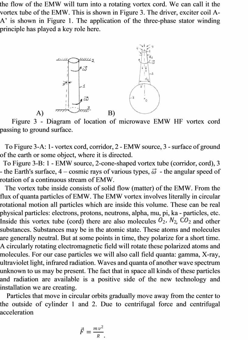
X(A-A’), Y(B-B’), Z(C-C’) is the geometry of the
location of the threewinding coil to create rotating magnetic field in a
circle. ![]() о.
о.
Figure 2 - Top view. F is the point of focus. The numbers are the same as in Figure 1.
Perpendicular variation magnetic field of ![]() is
imposed on the 2nd bunch of EMW leaving a wave guide outside. This field
rotates in a circle with a very high frequency
is
imposed on the 2nd bunch of EMW leaving a wave guide outside. This field
rotates in a circle with a very high frequency ![]() and causes, involves
in rotational circular movement all flow of EMW. Which flows out of channel 1
in direction X. EMW are spread along vortex corridor 1 - in Figures 3-А and 2 -
in Figure 3-В. Down towards the ground surface of the earth. At the same time
this stream of EMW entirely rotates around with an angular speed
and causes, involves
in rotational circular movement all flow of EMW. Which flows out of channel 1
in direction X. EMW are spread along vortex corridor 1 - in Figures 3-А and 2 -
in Figure 3-В. Down towards the ground surface of the earth. At the same time
this stream of EMW entirely rotates around with an angular speed ![]() . This stream
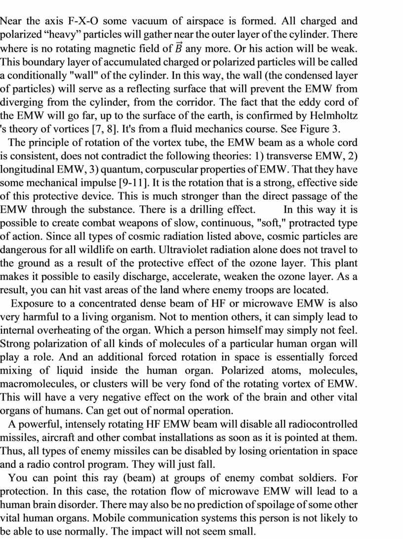
is continuous. In this way, the flow of the EMW will turn into a rotating
vortex cord. We can call it the vortex tube of the EMW. This is shown in Figure
3. The driver, exciter coil A-A’ is shown in Figure 1. The application of the
three-phase stator winding principle has played a key role here.
. This stream
is continuous. In this way, the flow of the EMW will turn into a rotating
vortex cord. We can call it the vortex tube of the EMW. This is shown in Figure
3. The driver, exciter coil A-A’ is shown in Figure 1. The application of the
three-phase stator winding principle has played a key role here.
А)  В)
В) 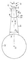
Figure 3 - Diagram of location of microwave EMW HF vortex cord passing to ground surface.
To Figure 3-А: 1- vortex cord, corridor, 2 - EMW source, 3 - surface of ground of the earth or some object, where it is directed.
To Figure 3-В: 1 - EMW source, 2-cone-shaped vortex
tube (corridor, cord), 3 - the Earth's surface, 4 – cosmic rays of various
types, ![]() - the angular speed of rotation of a
continuous stream of EMW.
- the angular speed of rotation of a
continuous stream of EMW.
The vortex tube inside consists of solid flow
(matter) of the EMW. From the flux of quanta particles of EMW. The EMW vortex
involves literally in circular rotational motion all particles which are inside
this volume. These can be real physical particles: electrons, protons,
neutrons, alpha, mu, pi, ka - particles, etc. Inside this vortex tube (cord)
there are also molecules ![]()
![]() ,
,
![]() and
other substances. Substances may be in the atomic state. These atoms and
molecules are generally neutral. But at some points in time, they polarize for
a short time. A circularly rotating electromagnetic field will rotate these
polarized atoms and molecules. For our case particles we will also call field
quanta: gamma, X-ray, ultraviolet light, infrared radiation. Waves and quanta
of another wave spectrum unknown to us may be present. The fact that in space
all kinds of these particles and radiation are available is a positive side of
the new technology and installation we are creating.
and
other substances. Substances may be in the atomic state. These atoms and
molecules are generally neutral. But at some points in time, they polarize for
a short time. A circularly rotating electromagnetic field will rotate these
polarized atoms and molecules. For our case particles we will also call field
quanta: gamma, X-ray, ultraviolet light, infrared radiation. Waves and quanta
of another wave spectrum unknown to us may be present. The fact that in space
all kinds of these particles and radiation are available is a positive side of
the new technology and installation we are creating.
Particles that move in circular orbits gradually move away from the center to the outside of cylinder 1 and 2. Due to centrifugal force and centrifugal acceleration
![]() .
.
Near the axis F-X-O some vacuum of airspace is
formed. All charged and polarized “heavy” particles will gather near the outer
layer of the cylinder. There where is no rotating magnetic field of ![]() any
more. Or his action will be weak. This boundary layer of accumulated charged or
polarized particles will be called a conditionally "wall" of the
cylinder. In this way, the wall (the condensed layer of particles) will serve
as a reflecting surface that will prevent the EMW from diverging from the
cylinder, from the corridor. The fact that the eddy cord of the EMW will go
far, up to the surface of the earth, is confirmed by Helmholtz 's theory of
vortices [7, 8]. It's from a fluid mechanics course. See Figure 3.
any
more. Or his action will be weak. This boundary layer of accumulated charged or
polarized particles will be called a conditionally "wall" of the
cylinder. In this way, the wall (the condensed layer of particles) will serve
as a reflecting surface that will prevent the EMW from diverging from the
cylinder, from the corridor. The fact that the eddy cord of the EMW will go
far, up to the surface of the earth, is confirmed by Helmholtz 's theory of
vortices [7, 8]. It's from a fluid mechanics course. See Figure 3.
The principle of rotation of the vortex tube, the EMW beam as a whole cord is consistent, does not contradict the following theories: 1) transverse EMW, 2) longitudinal EMW, 3) quantum, corpuscular properties of EMW. That they have some mechanical impulse [9-11]. It is the rotation that is a strong, effective side of this protective device. This is much stronger than the direct passage of the EMW through the substance. There is a drilling effect. In this way it is possible to create combat weapons of slow, continuous, "soft," protracted type of action. Since all types of cosmic radiation listed above, cosmic particles are dangerous for all wildlife on earth. Ultraviolet radiation alone does not travel to the ground as a result of the protective effect of the ozone layer. This plant makes it possible to easily discharge, accelerate, weaken the ozone layer. As a result, you can hit vast areas of the land where enemy troops are located.
Exposure to a concentrated dense beam of HF or microwave EMW is also very harmful to a living organism. Not to mention others, it can simply lead to internal overheating of the organ. Which a person himself may simply not feel. Strong polarization of all kinds of molecules of a particular human organ will play a role. And an additional forced rotation in space is essentially forced mixing of liquid inside the human organ. Polarized atoms, molecules, macromolecules, or clusters will be very fond of the rotating vortex of EMW. This will have a very negative effect on the work of the brain and other vital organs of humans. Can get out of normal operation.
A powerful, intensely rotating HF EMW beam will disable all radiocontrolled missiles, aircraft and other combat installations as soon as it is pointed at them. Thus, all types of enemy missiles can be disabled by losing orientation in space and a radio control program. They will just fall.
You can point this ray (beam) at groups of enemy combat soldiers. For protection. In this case, the rotation flow of microwave EMW will lead to a human brain disorder. There may also be no prediction of spoilage of some other vital human organs. Mobile communication systems this person is not likely to be able to use normally. The impact will not seem small.
Sources of microwave EMW can be magnetrons, which are described in [14]. Figure 1-С - corresponds not to magnetron, but to weaker low-frequency radiation. For example, it is a powerful radio lamp (GU type) with an output to the L-C cascade. It is also possible to use klystrons and lamps of travelling and reflected waves with a high frequency.
Sometimes there is a need to change the relation
of output and entrance diameters of an output section of the pipe in Figure 1, ![]() .
For such expanding or narrowing contours we propose to perform internal
contours according to Vitoshinsky profile [7, 8]. The main flexible profile is
obtained, see Figure 1 - B, profile 2. Winding A-A’ is desirably arranged
closer to the narrow (smaller) part of loop 2.
That there was the best penetration of field
.
For such expanding or narrowing contours we propose to perform internal
contours according to Vitoshinsky profile [7, 8]. The main flexible profile is
obtained, see Figure 1 - B, profile 2. Winding A-A’ is desirably arranged
closer to the narrow (smaller) part of loop 2.
That there was the best penetration of field ![]() in depth of the
channel.
in depth of the
channel.
In the development of magnetrons for the creation of powerful EMW beams, Soviet physicists, led by academician V. L. Bonch-Bruevich, played an active role [1-4].
Let us record the law of electromagnetic field energy conservation for cylindrical column 2 in Figure 3- B) [9 - 11].
In steady-state case between sections 2 and 3
(Figure 3-А) there will be constant value of volumetric density of wave energy
(![]() )
[9 - 11]
)
[9 - 11]
![]()
![]() ,
(1)
,
(1)
where ![]() ,
, ![]() - are effective
values.
- are effective
values.
This means that the energy flows multiplied by the dimensions of the cross sections in sections 2 and 6 will be constant
![]() ,
(2)
,
(2)
![]() -average value of energy flow, refer to
Figure 4,
-average value of energy flow, refer to
Figure 4, ![]() - transverse area of the jet in this
section.
- transverse area of the jet in this
section.
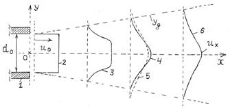
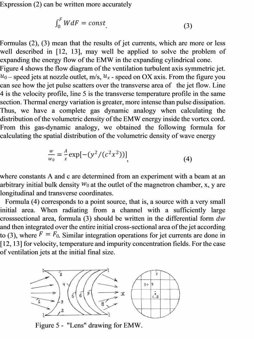
Figure 4 - Flow diagram of turbulent ventilation jet.
Expression (2) can be written more accurately
![]() .
(3)
.
(3)
Formulas (2), (3) mean that the results of jet currents, which are more or less well described in [12, 13], may well be applied to solve the problem of expanding the energy flow of the EMW in the expanding cylindrical cone.
Figure 4 shows the flow diagram of the ventilation
turbulent axis symmetric jet. ![]() – speed jets at nozzle outlet, m/s,
– speed jets at nozzle outlet, m/s, ![]() -
speed on OX axis. From the figure you can see how the jet pulse scatters over
the transverse area of the jet flow. Line 4 is the velocity profile, line 5
is the transverse temperature profile in the same section. Thermal energy
variation is greater, more intense than pulse dissipation. Thus, we have a
complete gas dynamic analogy when calculating the distribution of the
volumetric density of the EMW energy inside the vortex cord. From this
gas-dynamic analogy, we obtained the following formula for calculating the
spatial distribution of the volumetric density of wave energy
-
speed on OX axis. From the figure you can see how the jet pulse scatters over
the transverse area of the jet flow. Line 4 is the velocity profile, line 5
is the transverse temperature profile in the same section. Thermal energy
variation is greater, more intense than pulse dissipation. Thus, we have a
complete gas dynamic analogy when calculating the distribution of the
volumetric density of the EMW energy inside the vortex cord. From this
gas-dynamic analogy, we obtained the following formula for calculating the
spatial distribution of the volumetric density of wave energy
![]() ,
(4)
,
(4)
where constants A and c are determined from an
experiment with a beam at an arbitrary initial bulk density ![]() at the
outlet of the magnetron chamber, x, y are longitudinal and transverse coordinates.
at the
outlet of the magnetron chamber, x, y are longitudinal and transverse coordinates.
Formula (4) corresponds to a point source, that
is, a source with a very small initial area. When radiating from a channel with
a sufficiently large crosssectional area, formula (3) should be written in the
differential form ![]() and then integrated over the entire
initial cross-sectional area of the jet according to (3), where
and then integrated over the entire
initial cross-sectional area of the jet according to (3), where ![]() . Similar
integration operations for jet currents are done in [12, 13] for velocity,
temperature and impurity concentration fields. For the case of ventilation jets
at the initial final size.
. Similar
integration operations for jet currents are done in [12, 13] for velocity,
temperature and impurity concentration fields. For the case of ventilation jets
at the initial final size.
Figure 5 - "Lens" drawing for EMW.
Figure 5 shows the diagram of the refractive "lens" for electromagnetic waves - EMW. 2 shows a solid cylindrical body of metallic material which reflects the EMW well. 3-7 are thin metal wire grids that also reflect EMW well. These grids in the inlet and outlet have bulges in the interior of the cylinder or otherwise of the reflective channel. These bulges are directed in different directions, what is at the entrance and what is at the exit. Thus, this design, conventionally called by us "lens for EMW," a slightly divergent beam of EMW at the input will radiate pen in the form of a slightly convergent beam of EMW at the output.
Sources [1-4] note that magnetrons are used in radars. They operate in the mode of short-term pulses. This prevents the electrodes from overheating. Wavelengths are on the order of several centimeters. Capacity can reach up to a thousand kilowatts [1-4].
Formula (1) is just one member of the following general equation [9-11]
![]() ,
(5) when
,
(5) when
![]() ,
,
![]() ,
,
![]() .
.
(5) - represents the general law of energy
conservation in the final volume of the airspace in the presence of an
alternating electromagnetic field. Taking into account the emerging currents.
There are no cross flows w on the boundary line ![]() . They are considered
negligible, see Figure 4.
. They are considered
negligible, see Figure 4.
We are able to solve almost arbitrary systems of integral and differential equations in partial derivatives. Based on numerical methods. With a run of the values of the first derivatives at each point of the grid area [13].
The author expresses his readiness to cooperate if any organizations or people from all over the world show interest in these my scientific developments. We will implement and use together. Thank you for your attention.
Conclusions.
1. The new idea that the continuous flow of HF EMW can be superimposed from the outside perpendicular to the alternating magnetic field rotating in a circle was physically substantiated. Which will cause the entire continuous flow of the HF EMW as a whole vortex cord to rotate.
2. Possible options for using this new technical installation for protective purposes, in defensive hostilities have been analyzed. In the form of electronic blocking of all combat vehicles, missiles and shells. It can also be used to block the physical and mental activity of soldiers by affecting the brain and other vital organs of human functional activity.
3. A structural scheme for a refractive "lens for EMW" is proposed.
4. On the basis of gas-dynamic analogy semi-empirical formulas are obtained. Which allow to calculate spatial distribution of volumetric density of wave energy. In cylindrical coordinates (x, y).
Literature
1. Zherebtsov I. P. Basics of Electronics. - Leningrad: Energoatomizdat, 1989. - 352 p.
2. Izyumov N. M., Linde D. P. Basics of Radio Engineering. - M.-L.: Energy, 1965.- 479 p.
3. Putilov K. A. Physics course. T. 2. Teaching about electricity. – M.: State Publishing House of Physical-Mathematical Literature, 1962. - 584 p.
4. Pchelnikov Yu. N., Sviridov V.T. Electronics of high frequency. -M. Radio and communications -1981.-96 s.
5. Evsyukov A. A. Electrical Engineering. -M.: Enlightenment, 1979. - 248 p.
6. Pantyushin V. S. (editor) et al. General Electrical Engineering. M.: Higher School, 1970. - 568 p.
7. Povh I. L. Technical hydromechanical. - L.: Mechanical Engineering, 1969. - 524 p.
8. Povh I. L. Aerodynamic Experiment in Mechanical Engineering. - L.: Mechanical Engineering, 1974. - 480 p.
9. Nikolsky V. V. Electrodynamics and Propagation of Radio Waves. – M.: Science, 1973 - 607 p.
10. Penner D. I., Ugarov V. A. Electrodynamics and the special theory of relativity. - M.: Enlightenment, 1980.-271 p.
11. Multanovsky V.V., Vasilevsky A.S. Classical electrodynamics. - M.: Enlightenment, 1990. - 271 p.
12. Zhakatayev T. A., Kakimova K. Sh. Theory and calculation of turbulent ventilation jets and some practical problems of heat and mass exchange and combustion//https://znanio.ru/media/theory-and-calculation-of-turbulentventilation-jets-and-some-practical-problems-of-heat-and-mass-exchange-andcombustion-2624918
13. Zhakatayev T. A. Nonlinear models of hydrodynamics, heat and mass exchange and combustion in the tasks of diagnostics and control of metallurgical processes. - Dissertation for the degree of Doctor of Technical Sciences. - Karaganda: Chemical and Metallurgical Institute named after J. Abishev. – 2010.
Summary
Zhakatayev T. A., Kakimova K. Sh. A new type of protective weapon based on the creation of a rotating Powerful intensive beam of electromagnetic waves (EMW) high frequencies (HF) Microwave. A physical justification has been made for the new idea that a perpendicular alternating magnetic field rotating in a circle can be superimposed on the outside on the continuous directional flow of the U-HF EMW. Which will cause the entire continuous flow of the HF EMW as a whole vortex cord to rotate. Possible options for using this new technical installation for protective purposes, in defensive hostilities have been analyzed. Like electronic blocking of all combat vehicles, missiles and shells. It can also be used to block the physical and mental activity of soldiers by affecting the brain and other vital organs of human functional activity. Semiempirical formulas are given for calculating the spatial flow of EMW as a function of two cylindrical coordinates.
![Sources of microwave EMW can be magnetrons, which are described in [14]](https://fs.znanio.ru/d5af0e/c7/7a/21f7e0c85285e52206f3fd7ec363b8e012.jpg)
Материалы на данной страницы взяты из открытых источников либо размещены пользователем в соответствии с договором-офертой сайта. Вы можете сообщить о нарушении.