Поделиться

Magnetic field, electromagnetic induction
1. Calculate the force per centimetre length of a straight wire placed at right angles to a uniform magnetic field of magnetic flux density 0.12 T and carrying a current of 3.5 A. [3]
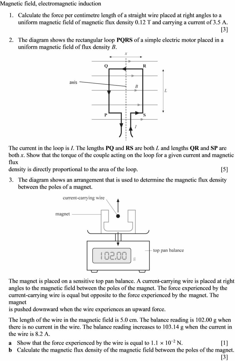
2.
The diagram shows the
rectangular loop PQRS of a simple electric motor placed in a
uniform magnetic field of flux density B.
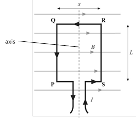
The current in the loop is I. The
lengths PQ and RS are both L and lengths QR and SP
are both x. Show that the torque of the couple acting on the loop for a
given current and magnetic flux
density is directly proportional to the area of the loop. [5]
3.
The diagram shows an
arrangement that is used to determine the magnetic flux density
between the poles of a magnet.
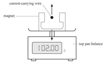
The magnet is
placed on a sensitive top pan balance. A current-carrying wire is placed at
right angles to the magnetic field between the poles of the magnet. The force
experienced by the current-carrying wire is equal but opposite to the force
experienced by the magnet. The magnet
is pushed downward when the wire experiences an upward force.
The length of
the wire in the magnetic field is 5.0 cm. The balance reading is 102.00 g when
there is no current in the wire. The balance reading increases to 103.14 g when
the current in
the wire is 8.2 A.
a Show that the force experienced by the wire is equal to 1.1 ´ 10−2 N. [1]
b Calculate the magnetic flux density of the magnetic field between the poles of the magnet. [3]
4.
Calculate the force
experienced by an electron travelling at a velocity of 4.0 ´ 106 m s−1
at right angles to a magnetic field of magnetic flux density 0.18 T. [3]
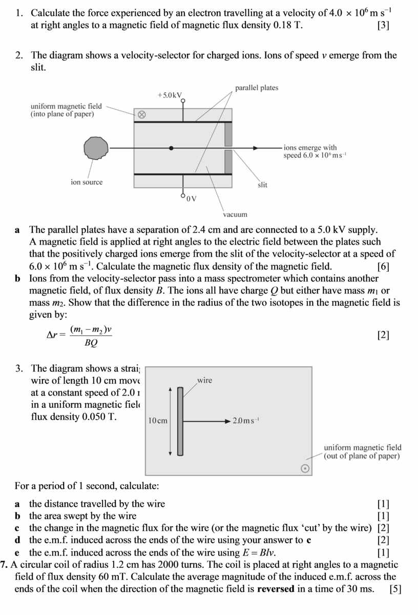
5. The diagram shows a velocity-selector for charged ions. Ions of speed v emerge from the slit.
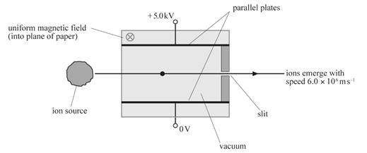
a The parallel plates have a separation
of 2.4 cm and are connected to a 5.0 kV supply.
A magnetic field is applied at right angles to the electric field between the
plates such
that the positively charged ions emerge from the slit of the velocity-selector
at a speed of 6.0 ´ 106 m s−1.
Calculate the magnetic flux density of the magnetic field. [6]
b Ions from the velocity-selector pass into a mass spectrometer which contains another magnetic field, of flux density B. The ions all have charge Q but either have mass m1 or mass m2. Show that the difference in the radius of the two isotopes in the magnetic field is given by:
Δr
= ![]() [2]
[2]
6.
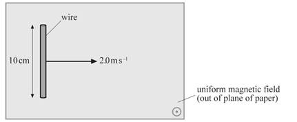 The diagram shows a straight
wire of length 10 cm moved
at a constant speed of 2.0 m s−1
in a uniform magnetic field of
flux density 0.050 T.
For a period of 1 second, calculate:
a the distance travelled by the wire [1]
b the area swept by the wire [1]
c the change in the magnetic flux for the wire (or the magnetic flux ‘cut’ by the wire) [2]
d the e.m.f. induced across the ends of the wire using your answer to c [2]
e the e.m.f. induced across the ends of the wire using E = Blv. [1]
7. A circular coil of radius 1.2 cm has 2000
turns. The coil is placed at right angles to a magnetic field of flux density
60 mT. Calculate the average magnitude of the induced e.m.f. across the
ends of the coil when the direction of the magnetic field is reversed in
a time of 30 ms. [5]
Материалы на данной страницы взяты из открытых источников либо размещены пользователем в соответствии с договором-офертой сайта. Вы можете сообщить о нарушении.