Поделиться

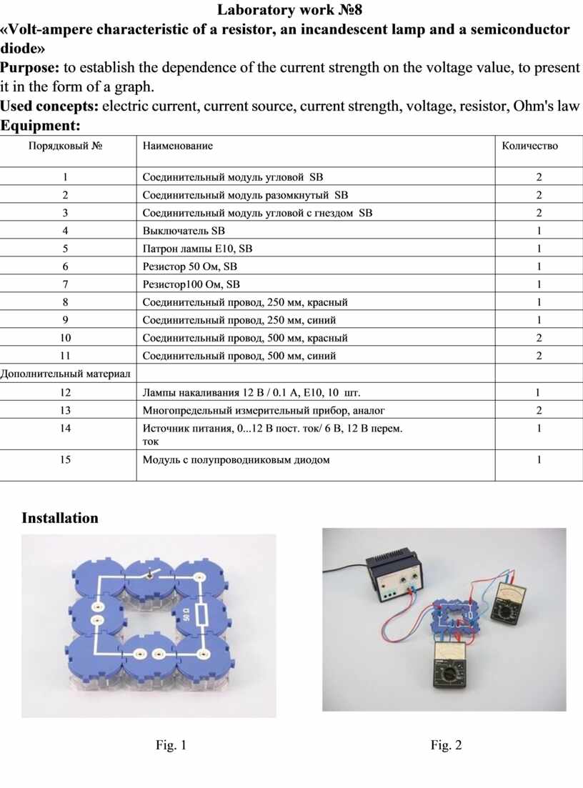
Laboratory work №8
«Volt-ampere characteristic of a resistor, an incandescent lamp and a semiconductor diode»
Purpose: to establish the dependence of the current strength on the voltage value, to present it in the form of a graph.
Used concepts: electric current, current source, current strength, voltage, resistor, Ohm's law
Equipment:
|
Порядковый № |
Наименование |
Количество |
|
1 |
Соединительный модуль угловой SB |
2 |
|
2 |
Соединительный модуль разомкнутый SB |
2 |
|
3 |
Соединительный модуль угловой с гнездом SB |
2 |
|
4 |
Выключатель SB |
1 |
|
5 |
Патрон лампы E10, SB |
1 |
|
6 |
Резистор 50 Oм, SB |
1 |
|
7 |
Резистор100 Oм, SB |
1 |
|
8 |
Соединительный провод, 250 мм, красный |
1 |
|
9 |
Соединительный провод, 250 мм, синий |
1 |
|
10 |
Соединительный провод, 500 мм, красный |
2 |
|
11 |
Соединительный провод, 500 мм, синий |
2 |
|
Дополнительный материал |
|
|
|
12 |
Лампы накаливания 12 В / 0.1 A, E10, 10 шт. |
1 |
|
13 |
Многопредельный измерительный прибор, аналог |
2 |
|
14 |
Источник питания, 0...12 В пост. ток/ 6 В, 12 В перем. ток |
1 |
|
15 |
Модуль с полупроводниковым диодом |
1 |
Installation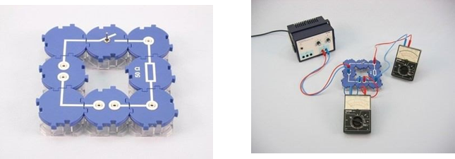
Fig. 1 Fig. 2
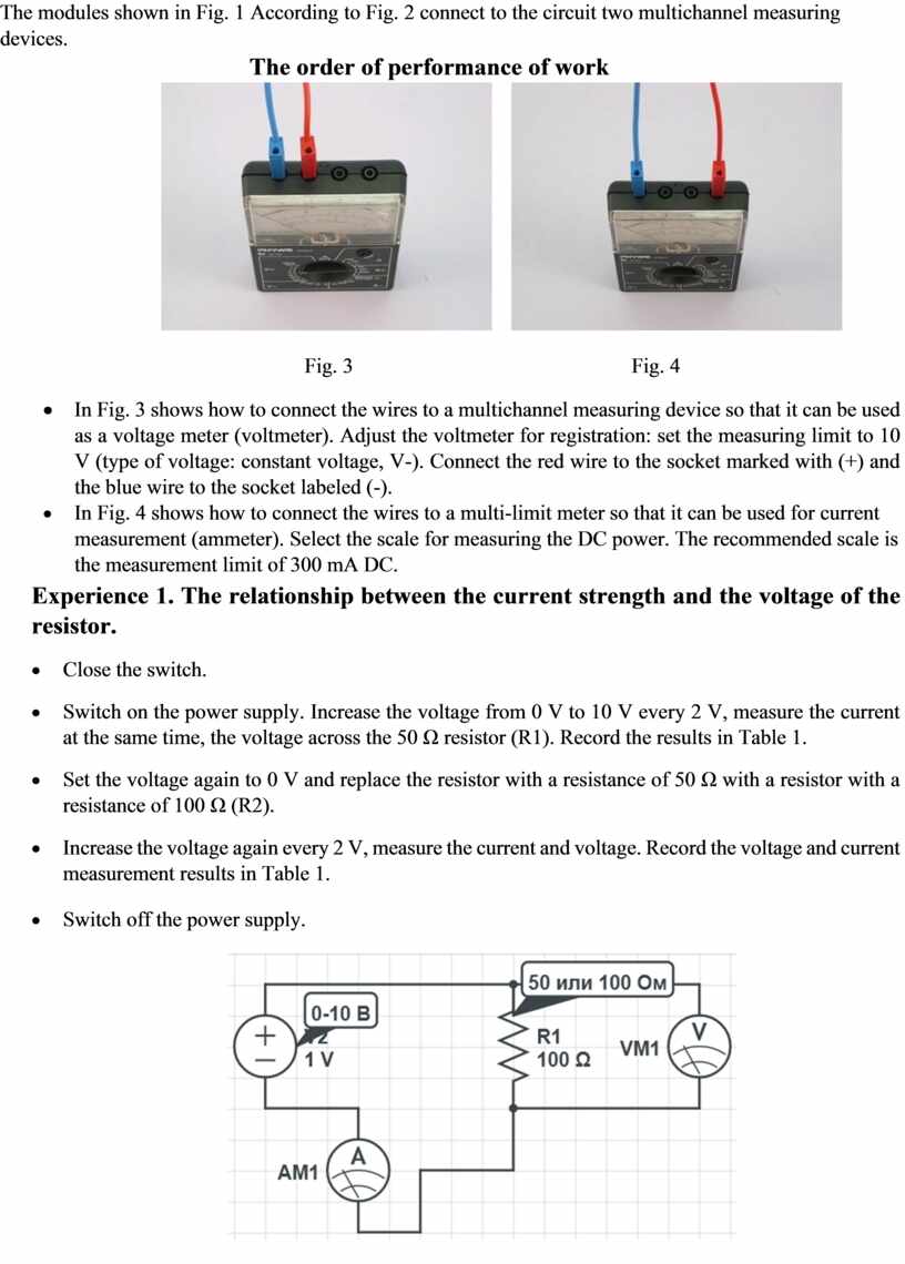
The modules shown in Fig. 1 According to Fig. 2 connect to the circuit two multichannel measuring devices.
The order of performance of work
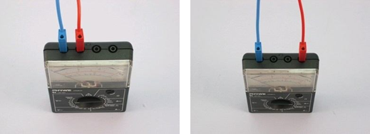
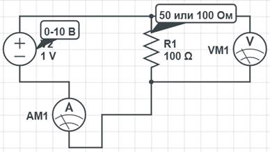
Fig. 3 Fig. 4
· In Fig. 3 shows how to connect the wires to a multichannel measuring device so that it can be used as a voltage meter (voltmeter). Adjust the voltmeter for registration: set the measuring limit to 10 V (type of voltage: constant voltage, V-). Connect the red wire to the socket marked with (+) and the blue wire to the socket labeled (-).
· In Fig. 4 shows how to connect the wires to a multi-limit meter so that it can be used for current measurement (ammeter). Select the scale for measuring the DC power. The recommended scale is the measurement limit of 300 mA DC.
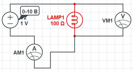
Experience 1. The relationship between the current strength and the voltage of the resistor.
· Close the switch.
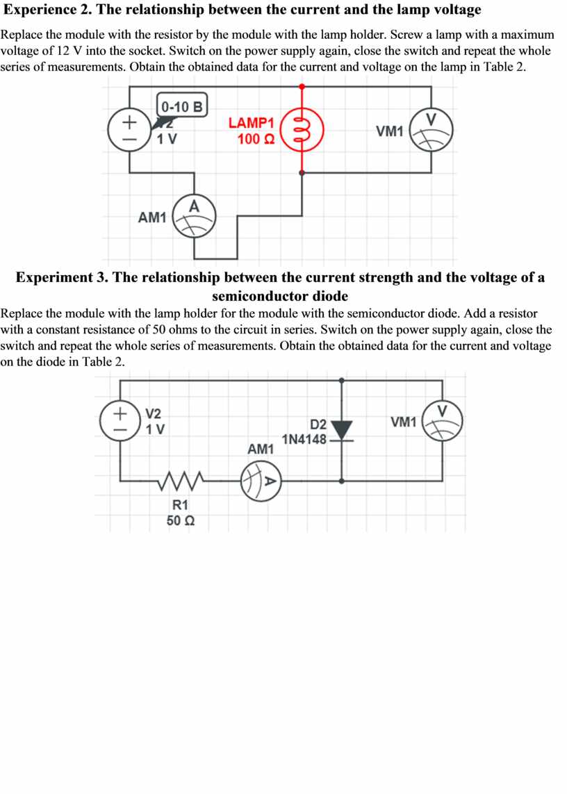
Replace the module with the resistor by the module with the lamp holder. Screw a lamp with a maximum voltage of 12 V into the socket. Switch on the power supply again, close the switch and repeat the whole series of measurements. Obtain the obtained data for the current and voltage on the lamp in Table 2.
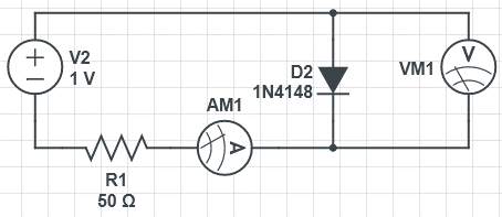
Experiment 3. The relationship between the current strength and the voltage of a semiconductor diode
Replace the module with the lamp holder for the module with the semiconductor diode. Add a resistor with a constant resistance of 50 ohms to the circuit in series. Switch on the power supply again, close the switch and repeat the whole series of measurements. Obtain the obtained data for the current and voltage on the diode in Table 2.
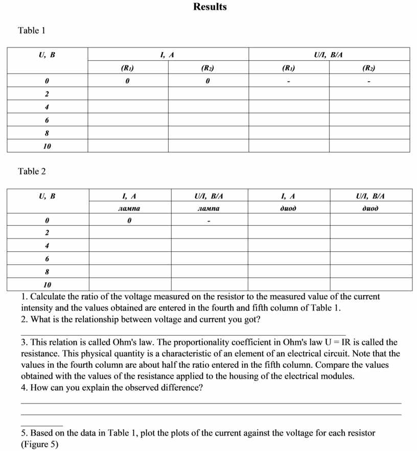
Results
Table 1
|
U, В |
|
I, А |
|
|
U/I, В/А |
|
||
|
(R1) |
|
|
(R2) |
(R1) |
|
|
(R2) |
|
|
0 |
0 |
|
|
0 |
- |
|
|
- |
|
2 |
|
|
|
|
|
|
|
|
|
4 |
|
|
|
|
|
|
|
|
|
6 |
|
|
|
|
|
|
|
|
|
8 |
|
|
|
|
|
|
|
|
|
10 |
|
|
|
|
|
|
|
|
Table 2
|
U, В |
I, А |
U/I, В/А |
I, А |
U/I, В/А |
|
лампа |
лампа |
диод |
диод |
|
|
0 |
0 |
- |
|
|
|
2 |
|
|
|
|
|
4 |
|
|
|
|
|
6 |
|
|
|
|
|
8 |
|
|
|
|
|
10 |
|
|
|
|
1. Calculate the ratio of the voltage measured on the resistor to the measured value of the current intensity and the values obtained are entered in the fourth and fifth column of Table 1.
2. What is the relationship between voltage and current you got?
______________________________________________________________________
3. This relation is called Ohm's law. The proportionality coefficient in Ohm's law U = IR is called the resistance. This physical quantity is a characteristic of an element of an electrical circuit. Note that the values in the fourth column are about half the ratio entered in the fifth column. Compare the values obtained with the values of the resistance applied to the housing of the electrical modules.
4. How can you explain the observed difference? _____________________________________________________________________________________________________________________________________________________________________________
5. Based on the data in Table 1, plot the plots of the current against the voltage for each resistor (Figure 5)

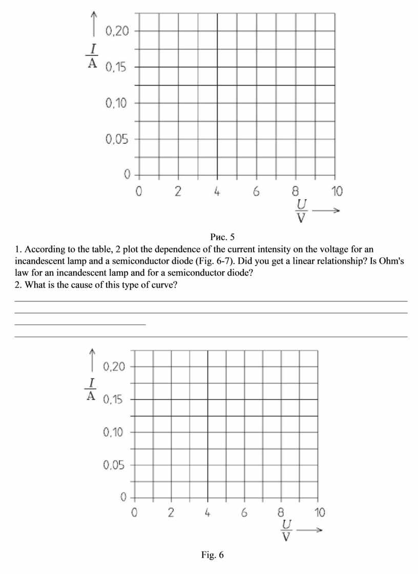
Рис. 5
1. According to the table, 2 plot the dependence of the current intensity on the voltage for an incandescent lamp and a semiconductor diode (Fig. 6-7). Did you get a linear relationship? Is Ohm's law for an incandescent lamp and for a semiconductor diode?
2. What is the cause of this type of curve? _____________________________________________________________________________________________________________________________________________________________________________________________
_________________________________________________________________________________
Fig. 6
Fig. 7
Материалы на данной страницы взяты из открытых источников либо размещены пользователем в соответствии с договором-офертой сайта. Вы можете сообщить о нарушении.