AP
Lenz's Law Hand Rule Sample Problems
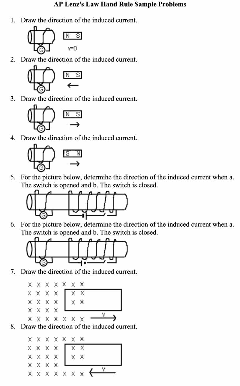
- Draw the direction of the induced
current.
- Draw the direction of the induced
current.
- Draw the direction of the induced
current.

- Draw the direction of the induced
current.
- For the picture below, determihe the
direction of the induced current when a. The switch is opened and b. The
switch is closed.
- For the picture below, determine the
direction of the induced current when a. The switch is opened and b. The
switch is closed.
- Draw the direction of the induced
current.
- Draw the direction of the induced
current.
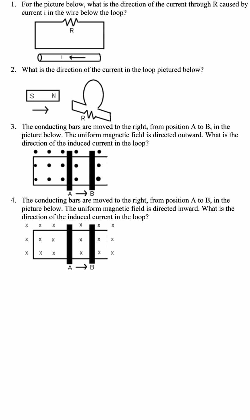
- For the picture below, what is the
direction of the current through R caused by current i in the wire below
the loop?
- What is the direction of the current in
the loop pictured below?
- The conducting bars are moved to the
right, from position A to B, in the picture below. The uniform magnetic
field is directed outward. What is the direction of the induced current in
the loop?
- The conducting bars are moved to the
right, from position A to B, in the picture below. The uniform magnetic
field is directed inward. What is the direction of the induced current in
the loop?
AP Electromagnetic Induction Sample
Problems
http://www.pschweigerphysics.com/APinducprob.html
- Consider
the arrangement shown below. Assume that R=6 W and l = 1.2 m. There is a
uniform 2.5 T magnetic field directed into the page. A 0.5 A current is
produced in the resistor. What voltage is induced in the bar? At what
speed should the bar be moved to produce a current of 0.5 A in the
resistor? At what rate is work done to keep the bar moving at this speed?
Ans: 3 V; 1.0 m/s; 1.5 W

- Two
long straight wires are separated by 0.120 m. The wires carry currents of
8 A in opposite directions; the current in the wire on the left is down
and that in the wire on the right is up. Find the magnitude and direction
of the net magnetic fields at points A, B, and C as
shown. Ans: 4.3 x 10⁻⁵ T, out, at A; 5.3 x 10⁻⁵ T,
in, at B; 6 x 10⁻⁵ T, in, at C
|
|
|
- A
square, single-turned coil 0.20 m on a side is placed with its plane
perpendicular to a constant magnetic field. An emf of 18 mV is induced
when he area of the coil decreases at a rate of 0.10 m2/s. What
is the magnitude of the magnetic field? Ans: 0.18 T
- The
sliding bar in the figure below has a length of 0.50 m and moves at 2 m/s
in a magnetic field of 0.25 T. Find the induced voltage in the moving rod.
If the resistance in the circuit is 0.50 W, find the current in the
circuit. Find the amount of energy dissipated by the resistor in one
second. The source of energy that is dissipated in the resistor is some
external agent that keeps the bar moving at a constant speed of 2 m/s by
exerting an applied force F. Find the value of F. Ans: 0.25 V; 0.50 A;
0.13 J; 0.063 N
- A
130 turn coil with a diameter of 2.1 cm is placed in a 0.0415 T magnetic
field. What is the magnetic flux through the coil? What is the value of
the induced emf if the magnetic field is reduced to zero in 50 msec? IF
the coil has a resistance of 4 W, what current flows through the coil as
the magnetic field is reduced? Ans: 1.44 x 10⁻⁵ Wb; 0.0375 V;
0.0093 A