Teacher Guides of the Lesson
Theoretical material for the lesson, definitions for concepts
Faraday’s and Lenz’s Law
Faraday’s experiments showed that the
emf induced by a change in magnetic flux depends on only a few factors.
First, emf is directly proportional to the change in flux ![]() . Second, emf is
greatest when the change in time
. Second, emf is
greatest when the change in time ![]() is smallest—that is,
emf is inversely proportional to
is smallest—that is,
emf is inversely proportional to ![]() . Finally, if a coil
has turns, an emf will be produced that is N times
greater than for a single coil, so that emf is directly proportional
to N. The equation for the emf induced by a change in magnetic flux
is
. Finally, if a coil
has turns, an emf will be produced that is N times
greater than for a single coil, so that emf is directly proportional
to N. The equation for the emf induced by a change in magnetic flux
is

This relationship is known as Faraday’s law of induction. The units for emf are volts, as is usual.
The minus sign in Faraday’s law of
induction is very important. The minus means that the emf creates a
current I and magnetic field B that oppose the change in flux ![]() —this is known as
Lenz’s law. The direction (given by the minus sign) of the emf is so
important that it is called Lenz’s law after the Russian
Heinrich Lenz (1804–1865), who, like Faraday and Henry, independently
investigated aspects of induction. Faraday was aware of the direction, but Lenz
stated it so clearly that he is credited for its discovery.
—this is known as
Lenz’s law. The direction (given by the minus sign) of the emf is so
important that it is called Lenz’s law after the Russian
Heinrich Lenz (1804–1865), who, like Faraday and Henry, independently
investigated aspects of induction. Faraday was aware of the direction, but Lenz
stated it so clearly that he is credited for its discovery.
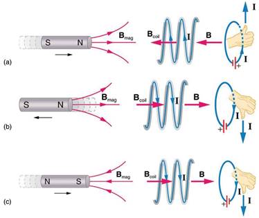
(a) When this bar magnet is thrust into the coil, the strength of the magnetic field increases in the coil. The current induced in the coil creates another field, in the opposite direction of the bar magnet’s to oppose the increase. This is one aspect of Lenz’s law—induction opposes any change in flux. (b) and (c) are two other situations. Verify for yourself that the direction of the induced Bind shown indeed opposes the change in flux and that the current direction shown is consistent with RHR-2.

Lenz’ law is a manifestation of the conservation of energy. The induced EMF produces a current that opposes the change in flux, because a change in flux means a change in energy. Energy can enter or leave, but not instantaneously. Lenz’ law is a consequence. As the change begins, the law says induction opposes and, thus, slows the change. In fact, if the induced EMF were in the same direction as the change in flux, there would be a positive feedback that would give us free energy from no apparent source—conservation of energy would be violated.
Self Inductance
Self inductance is an effect that is noticed when a single coil experiences the effect of inductance.
Under the effects of self inductance and changes in current induce an EMF or electro-motive force in that same wire or coil, producing what is often termed a back-EMF.
As the effect is noticed in the same wire or coil that generated the magnetic field, the effect is known as self inductance.
Self-inductance definitions
There are various definitions associated with self inductance that are useful to mention.
· Self-inductance: Self inductance is defined as the phenomenon in which a change in electric current in a circuit produces an induced electro-motive-force in the same circuit.
· Self inductance unit: The self-inductance of a coil is said to be one henry if a current change of one ampere per second through a circuit produces an electro-motive force of one volt in the circuit.
Self-inductance basics
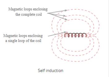
When current passes along a wire, and especially when it passes through a coil or inductor, a magnetic field is induced. This extends outwards from the wire or inductor and could couple with other circuits. However it also couples with the circuit from which it is set up.
The magnetic field can be envisaged as concentric loops of magnetic flux that surround the wire, and larger ones that join up with others from other loops of the coil enabling self-coupling within the coil.
When the current in the coil changes, this causes a voltage to be induced the different loops of the coil - the result of self-inductance.

In terms of quantifying the effect of the inductance, the basic formula below quantifies the effect.

Where:
VL = induced
voltage in volts
N = number of turns in the coil
dφ/dt = rate of change of
magnetic flux in webers / second

The induced voltage in an inductor may also be expressed in terms of the inductance (in henries) and the rate of change of current.
Self induction is the way in which single coils and chokes operate. A choke is used in radio frequency circuits because it opposes any change, i.e. the radio frequency signal, but allows any steady, i.e. DC current to flow.
Instructions for demonstrations and safety
Warning: experiments should be performed under the supervision of teachers or students followthe instructions of safety procedures.
Additional guidelines for organizing a lesson
1. Organization moment. Establishing emotional state. Checking for absent students.
2. Teacher introduces the topic and objectives of the lesson, assess criteria.
3. Teacher asks learners individually answer the CONCEPTUAL question. Individual students are called on to respond to questions and share their own opinions/thoughts.
4. Students practice with Lenz’s law problem.
5. The Teacher observes and assesses each student’s answer and provides fair and helpful feedback.
6. Set qualitative structured questions in which learners calculate the emf, current and magnetic flux linkage using Faraday’s Law of Induction, Ohm’s Law, Lenz’s Law.
7. Pairs checks and assesses each other’s answer and provides fair and helpful feedback by using an answer sheet.
8. At the end of the lesson students are encouraged to reflect on what they have learned and what they need to improve.
Recommendations for formative assessment
Activity1. Students discuss learning objectives and assess criteria.
Activity2. Learners individually answer the CONCEPTUAL question. Individual students are
called on to respond to questions and share their own opinions/thoughts.
Activity3. Students practice with Lenz’s law problem.
Activity4. The Teacher observes and assesses each student’s answer and provides fair and
helpful feedback.
Activity5. Set qualitative structured questions in which learners calculate the emf, current and
magnetic flux linkage using Faraday’s Law of Induction, Ohm’s Law, Lenz’s Law.
Activity6. Pairs checks and assesses each other’s answer and provides fair and helpful feedback
by using an answer sheet.
Activity7. At the end of the lesson students are encouraged to reflect on what they have
learned and what they need to improve.
Answers, criteria for assignments, additional materials for the lesson
1.


2.

List of useful links and literature
Douglas C. Giancoli, Physics Principles with Applications, Seventh edition 2014.
Keith Johnson Physics for You IGCSE Updated Edition 2011
AS and A level Physics, Cambridge University Press CIE Web site
Материалы на данной страницы взяты из открытых источников либо размещены пользователем в соответствии с договором-офертой сайта. Вы можете сообщить о нарушении.