Поделиться

|
Technology uses cyclic thermodynamic processes to describe the conversion of thermal energy to mechanical energy and vice versa. During this process a medium undergoes periodically different changes of state, such as compression and expansion, evaporation and condensation, or heating and cooling over a period of time. In a cyclic process, the medium, after having undergone the different changes of state, goes back to its original state and can thus be reused repeatedly. |
When a phase change occurs, more energy is converted than during simple heating or cooling. This means that phase change processes involve a higher energy density and require lower differences in temperature. Cyclic processes can be used in driving or driven machines. Driving machines convert thermal energy to mechanical energy, such as in steam power plants. Driven machines convert the supplied mechanical energy into thermal energy, like in a compression refrigeration system. |
Suitable media are substances
that remain in a permanent gaseous state during the cyclic process, such as air
or helium, or substances that change their aggregate state during the process
(phase change), like water, ammonia, fl uorocarbons, or CO2.
Representation of cyclic processes in state diagrams
|
A cyclic thermodynamic process can be illustrated clearly by what are known as state diagrams. The most commonly used state diagrams are: • p-v diagram: pressure p against specifi c volume v, suitable for representing mechanical power. It is often used for reciprocating compressors and internal combustion engines with a purely gaseous working medium. Here, cyclic processes can be observed quite well because there is a fi xed relationship between volume change and time. The enclosed area is a measure for the mechanical work performed, also known as useful work. • h-s diagram: enthalpy h against entropy s, for representation of steam turbine processes. It is used for water steam and is well suited as a tool for designing steam turbines. • log p-h diagram: logarithmic representation of the pressure p against the specifi c enthalpy h, particularly well suited for cooling processes in refrigeration engineering, as heat fl uxes |
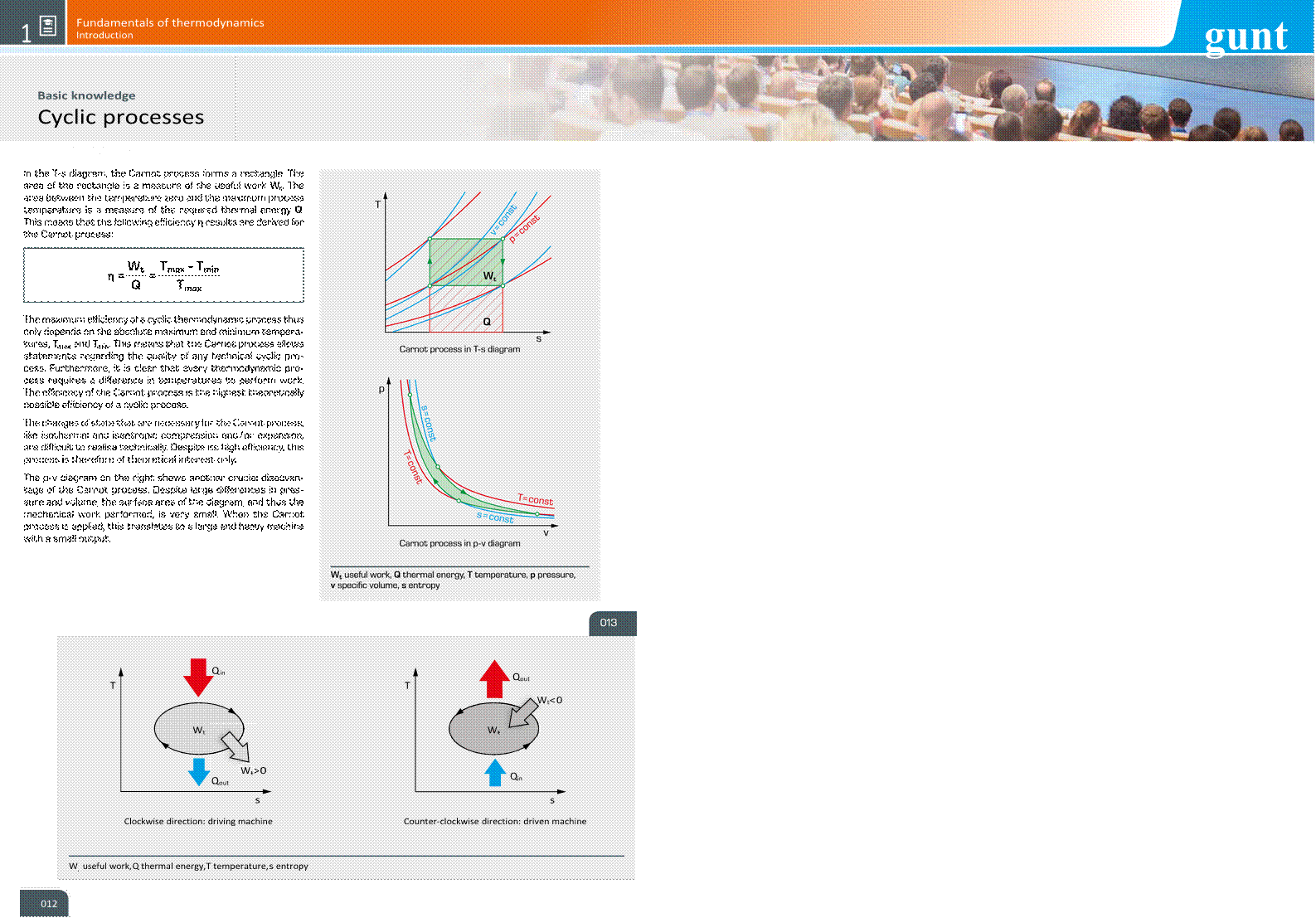
can be read from the diagram directly as horizontal lines. For the vertical pressure scale, a logarithmic division is used, as this is a good way to represent phase limit curves. • T-s diagram: a plot of temperature T against entropy s, used for the representation of the thermodynamic conditions. The direction of the cyclic process indicates the type of system, driving or driven machine. If the cycle goes clockwise, the system is a driving machine, and if it goes counter-clockwise, it is a driven machine. In the clockwise direction, heat is absorbed at a high temperature and released at a low temperature. In the counter-clockwise direction, heat is absorbed at a low temperature and released at a high temperature. If the system is operated in the counter-clockwise direction, it is thus suitable as a heat pump or refrigeration machine. As in the p-v diagram, the enclosed area is a measure of the useful work performed. |
|
Examples of cyclic thermodynamic processes |
|
|
|
|
Type |
Driving or driven machine |
Working medium |
Aggregate state |
|
Steam power plant |
driving |
water |
liquid/gaseous |
|
Internal combustion engine |
driving |
air/combustion gas |
gaseous |
|
Gas turbine |
driving |
air/combustion gas |
gaseous |
|
Stirling engine |
driving |
air, helium |
gaseous |
|
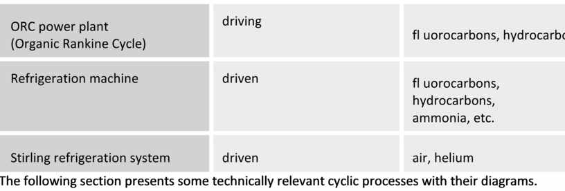
ORC power plant (Organic Rankine Cycle) |
driving |
fl uorocarbons, hydrocarbons |
liquid/gaseous |
|
Refrigeration machine |
driven |
fl uorocarbons, hydrocarbons, ammonia, etc. |
liquid/gaseous |
|
Stirling refrigeration system |
driven |
air, helium |
gaseous |
The following section presents some technically relevant cyclic processes with their diagrams.
|
|
|
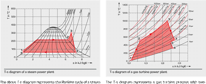
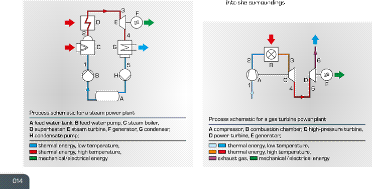
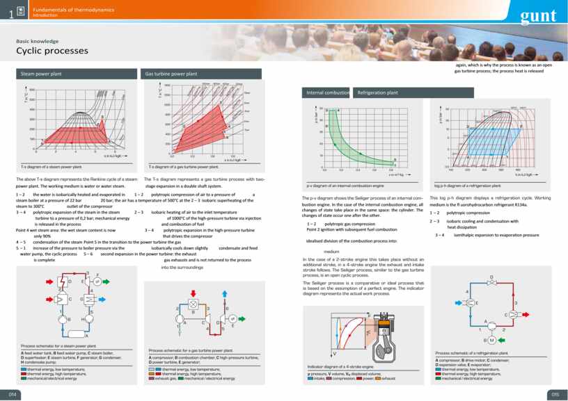
power plant. The working medium is water or water steam. stage expansion in a double shaft system.
1 – 2 the water is isobarically heated and evaporated in 1 – 2 polytropic compression of air to a pressure of a steam boiler at a pressure of 22 bar 20 bar; the air has a temperature of 500°C at the 2 – 3 isobaric superheating of the steam to 300°C outlet of the compressor
3 – 4 polytropic expansion of the steam in the steam 2 – 3 isobaric heating of air to the inlet temperature
turbine to a pressure of 0,2 bar; mechanical energy of 1000°C of the high-pressure turbine via injection
is released in the process and combustion of fuel
Point 4 wet steam area: the wet steam content is now 3 – 4 polytropic expansion in the high-pressure turbine
only 90% that drives the compressor
4 – 5 condensation of the steam Point 5 in the transition to the power turbine the gas
5

– 1 increase of the
pressure to boiler pressure via the isobarically cools
down slightly condensate and feed water pump, the cyclic process 5 – 6
second expansion in the power turbine: the exhaust
is complete gas exhausts and is not returned to the process
again, which is why the process is known as an open
gas turbine process; the process heat is released
|
|
|
|
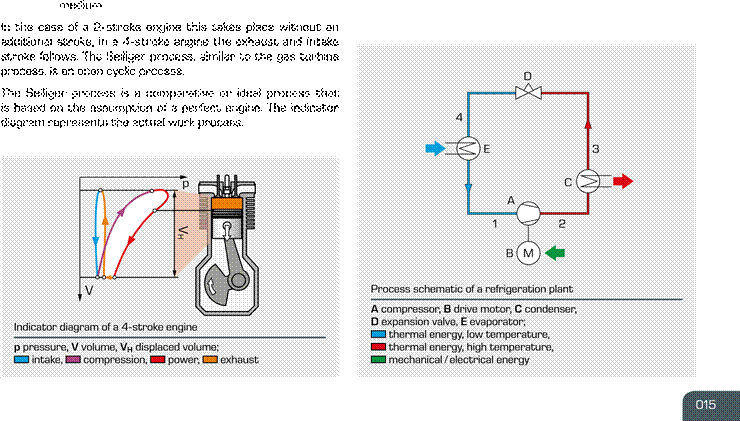
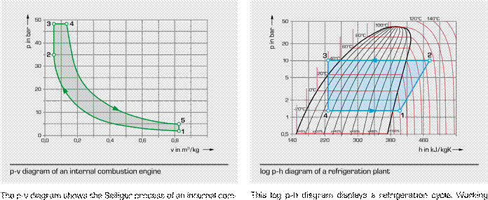
bustion engine. In the case of the internal combustion engine, all changes of state take place in the same space: the cylinder. The changes of state occur one after the other. 1 – 2 polytropic gas compression Point 2 ignition with subsequent fuel combustion |
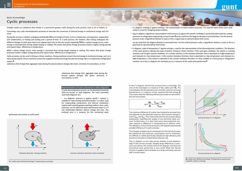
medium is the fl uorohydrocarbon refrigerant R134a. 1 – 2 polytropic compression 2 – 3 isobaric cooling and condensation with heat dissipation |
3 – 4 isenthalpic expansion to evaporation pressure
idealised division of the combustion process into:
2
 – 3 isochoric proportion of the
combustion process 4 – 1 isobaric evaporation with heat
absorption
– 3 isochoric proportion of the
combustion process 4 – 1 isobaric evaporation with heat
absorption
3 – 4 isobaric proportion of the combustion process
After being superheated to a certain degree the refrigerant
4 – 5 polytropic (isentropic) expansion, in this phase the vapour is once again sucked in and compressed by the com usefull work results pressor at point 1. The cyclic process ends.
5 – 1 isochoric decompression and exchange of working

Материалы на данной страницы взяты из открытых источников либо размещены пользователем в соответствии с договором-офертой сайта. Вы можете сообщить о нарушении.