Поделиться

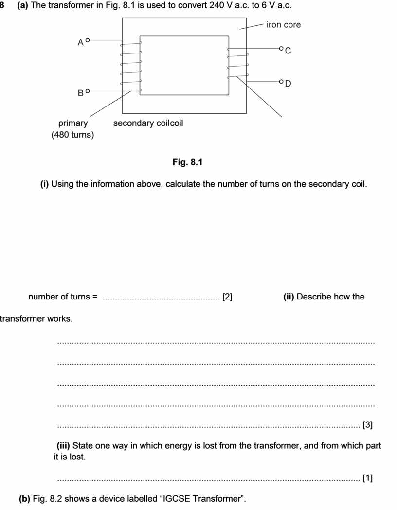
8 (a) The transformer in Fig. 8.1 is used to convert 240 V a.c. to 6 V a.c.
primary secondary coil coil
(480 turns)
(i) Using the information above, calculate the number of turns on the secondary coil.
number of turns = ................................................ [2] (ii) Describe how the transformer works.
..................................................................................................................................
..................................................................................................................................
..................................................................................................................................
..................................................................................................................................
............................................................................................................................ [3]
(iii) State one way in which energy is lost from the transformer, and from which part it is lost.
............................................................................................................................ [1]
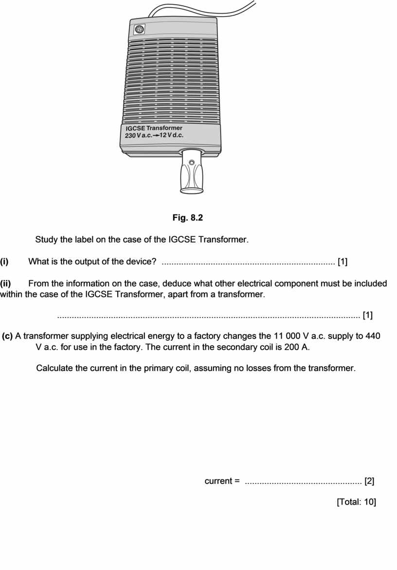
(b) Fig. 8.2 shows a device labelled “IGCSE Transformer”.
Study the label on the case of the IGCSE Transformer.
(i) What is the output of the device? ....................................................................... [1]
(ii) From the information on the case, deduce what other electrical component must be included within the case of the IGCSE Transformer, apart from a transformer.
............................................................................................................................ [1]
(c) A transformer supplying electrical energy to a factory changes the 11 000 V a.c. supply to 440 V a.c. for use in the factory. The current in the secondary coil is 200 A.
Calculate the current in the primary coil, assuming no losses from the transformer.
current = ................................................ [2]
[Total: 10]
[Turn over
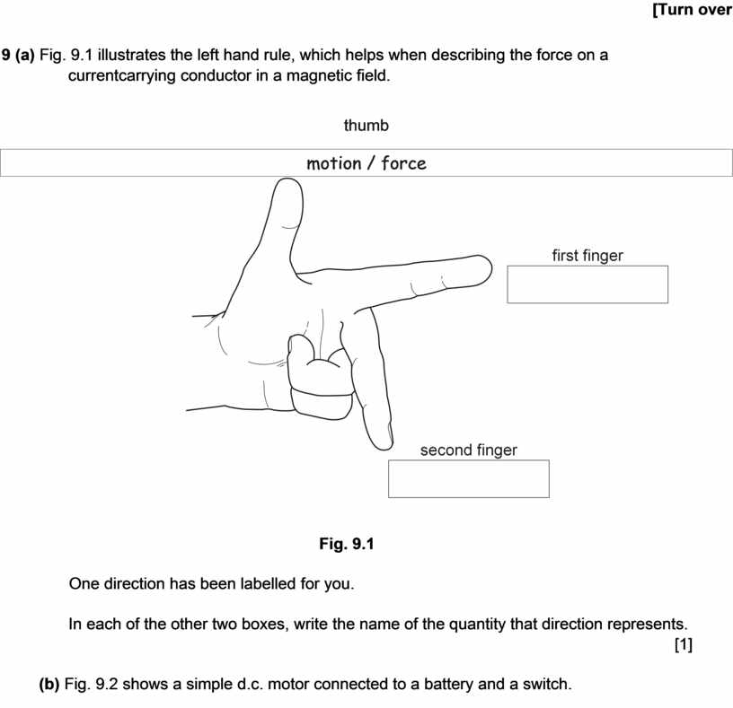
9 (a) Fig. 9.1 illustrates the left hand rule, which helps when describing the force on a currentcarrying conductor in a magnetic field.
thumb
One direction has been labelled for you.
In each of the other two boxes, write the name of the quantity that direction represents.
[1]
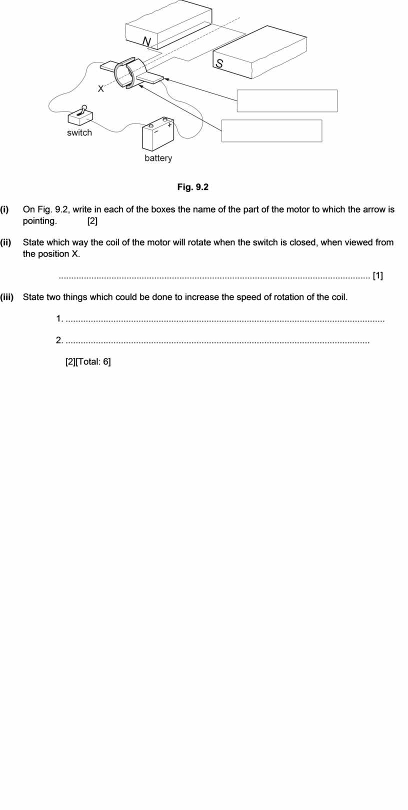
(b) Fig. 9.2 shows a simple d.c. motor connected to a battery and a switch.
(i) On Fig. 9.2, write in each of the boxes the name of the part of the motor to which the arrow is pointing. [2]
(ii) State which way the coil of the motor will rotate when the switch is closed, when viewed from the position X.
............................................................................................................................ [1]
(iii) State two things which could be done to increase the speed of rotation of the coil.
1. ...............................................................................................................................
2. ......................................................................................................................... [2][Total: 6]
[Turn over

Материалы на данной страницы взяты из открытых источников либо размещены пользователем в соответствии с договором-офертой сайта. Вы можете сообщить о нарушении.