Поделиться
|
Long-term plan unit: 10.4.109 |
School: |
|
|||||||
|
Date: |
Teacher name: |
|
|||||||
|
Grade: |
Number present: |
absent: |
|||||||
|
Theme of the lesson |
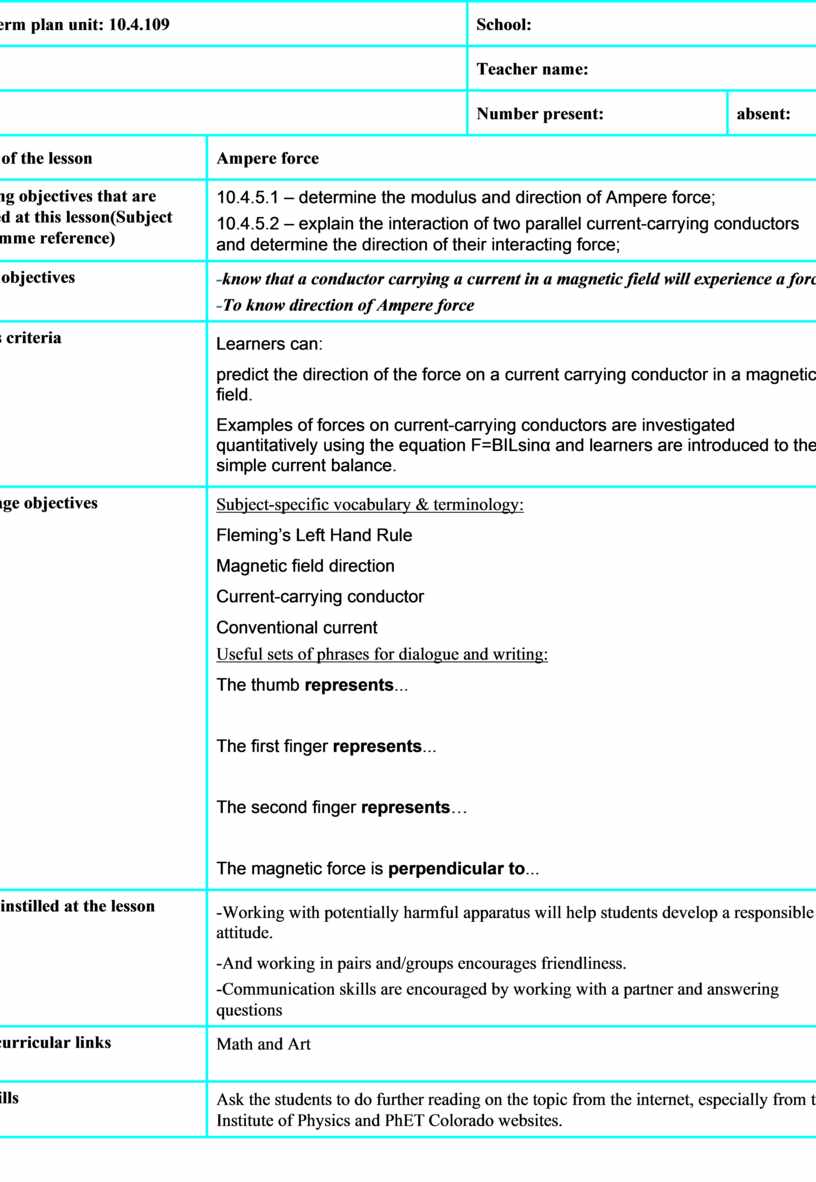
Ampere force |
|
|||||||
|
Learning objectives that are achieved at this lesson(Subject Programme reference) |
10.4.5.1 – determine the modulus and direction of Ampere force; 10.4.5.2 – explain the interaction of two parallel current-carrying conductors and determine the direction of their interacting force; |
|
|||||||
|
Lesson objectives |
-know that a conductor carrying a current in a magnetic field will experience a force -To know direction of Ampere force |
|
|||||||
|
Success criteria |
Learners can: predict the direction of the force on a current carrying conductor in a magnetic field. Examples of forces on current-carrying conductors are investigated quantitatively using the equation F=BILsinα and learners are introduced to the simple current balance. |
|
|||||||
|
Language objectives |
Subject-specific vocabulary & terminology: Fleming’s Left Hand Rule Magnetic field direction Current-carrying conductor Conventional current Useful sets of phrases for dialogue and writing: The thumb represents...
The first finger represents...
The second finger represents…
The magnetic force is perpendicular to... |
|
|||||||
|
Values instilled at the lesson |
-Working with potentially harmful apparatus will help students develop a responsible attitude. -And working in pairs and/groups encourages friendliness. -Communication skills are encouraged by working with a partner and answering questions |
|
|||||||
|
Cross-curricular links |
Math and Art |
|
|||||||
|
ICT skills |
Ask the students to do further reading on the topic from the internet, especially from the Institute of Physics and PhET Colorado websites. |
|
|||||||
|
Previous learning
|
Students will probably know that electric and gravitational fields are defined as the force on unit charge or mass. So by comparison, B = F/IL, and this gives a way of defining the 'magnetic field strength'. Physicists refer to this as the B-field or magnetic flux density which has units of NA-1m-1 or tesla (T). Students may already have seen the effect in your initial experimentsin 8 grade but this may need to be repeated here. The effect can be explained by considering the effect of the field produced by one conductor on the other and then reversing the argument. |
|
|||||||
|
Course of the lesson |
|
||||||||
|
Planned stages of the lesson |
Planned activities at the lesson |
Resources |
|
||||||
|
Beginning 15 minutes |
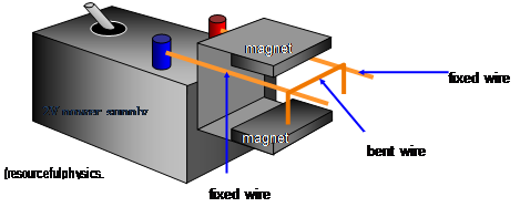
Having reminded your students that magnetic fields can be found near permanent magnets and in the presence of an electric current, the next step is to show how the ‘field’ can be quantified. Again, students should know that a conductor carrying a current in a magnetic field will experience a force and will probably remember that Fleming's Left Hand Rule can be used to find the direction of that force. Demonstrations:Leading to F = BIL.
|
fixed wire, bent wire, magnets, 2V power supply
|
|
||||||
|
Middle 15 minutes
|
Discussion: Factors affecting the force The experiments above lead to the conclusion that the force F on the conductor is proportional to the length of wire in the field, L, the current I and the ‘strength’ of the field, represented by the flux density B. (There is also an 'angle factor' to consider, but we will leave this aside for now.) Combining these we get F = BIL (It can help students to refer to this force as the ‘BIL force’.) Students will probably know that electric and gravitational fields are defined as the force on unit charge or mass. So by comparison, B = F/IL, and this gives a way of defining the 'magnetic field strength'. Physicists refer to this as the B-field or magnetic flux density which has units of NA-1m-1 or tesla (T). A field of 1T is a very strong field. The field between the poles of the Magnadur magnets that are used in the above experiment is about 3 ´ 10-2 T while the Earth's magnetic field is about 10-5 T. If your specification requires, you will need to develop the 'angle factor' seen in the experiment into the mathematical formula: F = BIL sin q. For the mathematically inclined, it can be shown that the effective length of the wire in the field (i.e. that which is at right angles) is L sinq. If students find this difficult, then it can be argued that the maximum force occurs when field and current are at right angles, q = 90o (sin q = 1), and that this falls to zero when field and current are parallel, q = 0o (sin q = 0). Formal definitions Some specifications require a formal definition of magnetic flux density and/or the tesla. The strength of a magnetic field or magnetic flux density B can be measured by the force per unit current per unit length acting on a current-carrying conductor placed perpendicular to the lines of a uniform magnetic field. The SI unit of magnetic flux density B is the tesla (T), equal to 1 NA–1m–1. This is the magnetic flux density if a wire of length 1m carrying a current of 1 A as a force of 1 N exerted on it in a direction perpendicular to both the flux and the current. Study of the force between parallel conductors leading to the definition of the ampere may be required. |
Slide |
|
||||||
|
End 10 min |
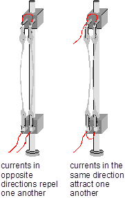
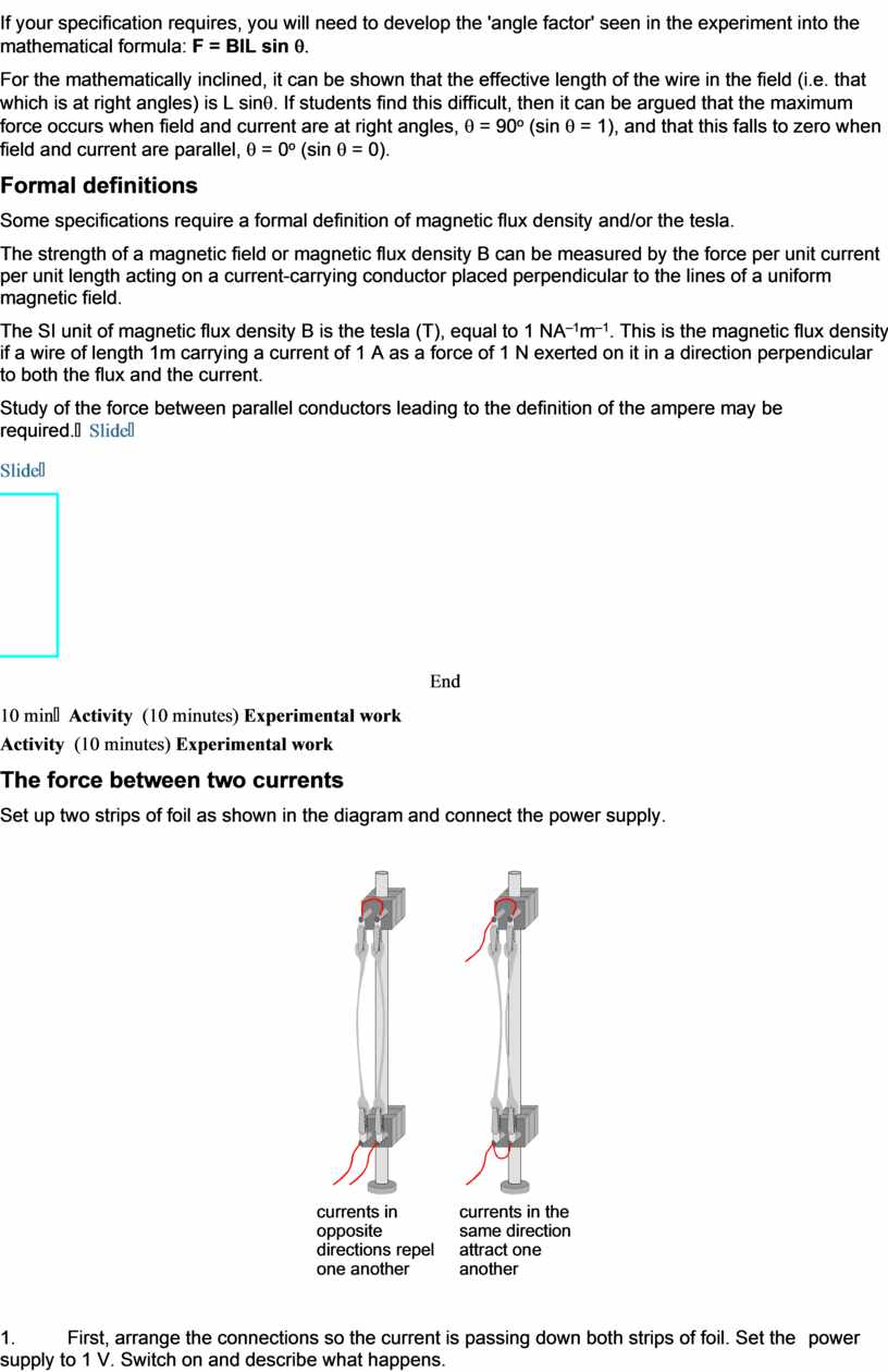
Activity (10 minutes) Experimental work The force between two currents Set up two strips of foil as shown in the diagram and connect the power supply.
1. First, arrange the connections so the current is passing down both strips of foil. Set the power supply to 1 V. Switch on and describe what happens. 2. Increase the power supply to 2 V. What happens now? 3. Arrange the connections so that the current is passing up both strips of foil. What happens? 4. Finally arrange the connections so the current is passing up one foil and down the other. What is the result?
Measurement Criteria
What you have seen 1. The size of the force between currents depends on the size of the current. 2. The direction of the force depends on the current directions. If they are in the same direction they attract. If they are in opposite directions, they repel. Like currents attract, unlike currents repel. |
The sucsess criteria’s table
fixed wire, , 2V power supply
|
|
||||||
|
Differentiation – how do you plan to give more support? How do you plan to challenge the more able learners? |
Assessment – how are you planning to check students’ learning? |
Health and safety regulations |
|
||||||
|
Differentiation can be by task, by outcome, by individual support, by selection of teaching materials and resources taking into account individual abilities of learners (Theory of Multiple Intelligences by Gardner). Differentiation can be used at any stage of the lesson keeping time management in mind.
|
Use this section to record the methods you will use to assess what students have learned during the lesson. |
Health promoting techniques Breaks and physical activities used. Points from Safety rules used at this lesson. Safety If the current is too large then the foil will get hot and the forces will be too large and tear the foil. When using two strips of foil be aware that if they touch sparking may occur. Care is needed, and the pd must remain modest |
|
||||||
|
Reflection
Were the lesson objectives/learning objectives realistic? Did all learners achieve the LO? If not, why? Did my planned differentiation work well? Did I stick to timings? What changes did I make from my plan and why?
|
Use the space below to reflect on your lesson. Answer the most relevant questions from the box on the left about your lesson. |
|
|||||||
|
|
|
||||||||
|
Summary evaluation
What two things went really well (consider both teaching and learning)? 1:
2:
What two things would have improved the lesson (consider both teaching and learning)? 1:
2:
What have I learned from this lesson about the class orachievements/difficulties of individuals that will inform my next lesson?
|
|
||||||||
Материалы на данной страницы взяты из открытых источников либо размещены пользователем в соответствии с договором-офертой сайта. Вы можете сообщить о нарушении.