Поделиться

Teacher Guides of the Lesson
Theoretical material for the lesson, definitions for concepts
INTRODUCTION
The dc motor is a mechanical workhorse that can be used in many different ways. Many large pieces of equipment depend on a dc motor for their power to move. The speed and direction of rotation of a dc motor are easily controlled. This makes it especially useful for operating equipment, such as winches, cranes, and missile launchers, which must move in different directions and at varying speeds.
PRINCIPLES OF OPERATION
The operation of a dc motor is based on the following principle:
A current-carrying conductor placed in a magnetic field, perpendicular to the lines of flux, tends to move in a direction perpendicular to the magnetic lines of flux.
There
is a definite relationship between the direction of the magnetic field, the
direction of current in the conductor, and the direction in which the conductor
tends to move. This relationship is best explained by using the RIGHT-HAND RULE
FOR MOTORS (fig. 2-1).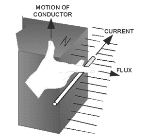
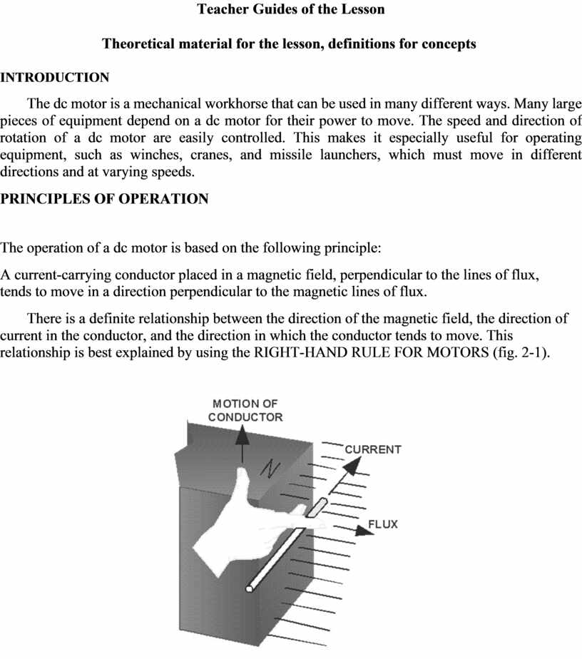
Figure 2-1.—Right-hand rule for motors.
To find the direction of motion of a conductor, extend the thumb, forefinger, and middle finger of your right hand so they are at right angles to each other. If the forefinger is pointed in the direction of magnetic flux (north to south) and the middle finger is pointed in the direction of current flow in the conductor, the thumb will point in the direction the conductor will move.
Stated very simply, a dc motor rotates as a result of two magnetic fields interacting with each other. The armature of dc motor acts like an electromagnet when current flows through its coils. Since the armature is located within the magnetic field of the field poles, these two magnetic fields interact. Like magnetic poles repel each other, and unlike magnetic poles attract each other. As in the dc generator, the dc motor has field poles that are stationary and an armature that turns on bearings in the space between the field poles. The armature of a dc motor has windings on it just like the armature of a dc generator. These windings are also connected to commutator segments. A dc motor consists of the same components as a dc generator. In fact, most dc generators can be made to act as motors, and vice versa.
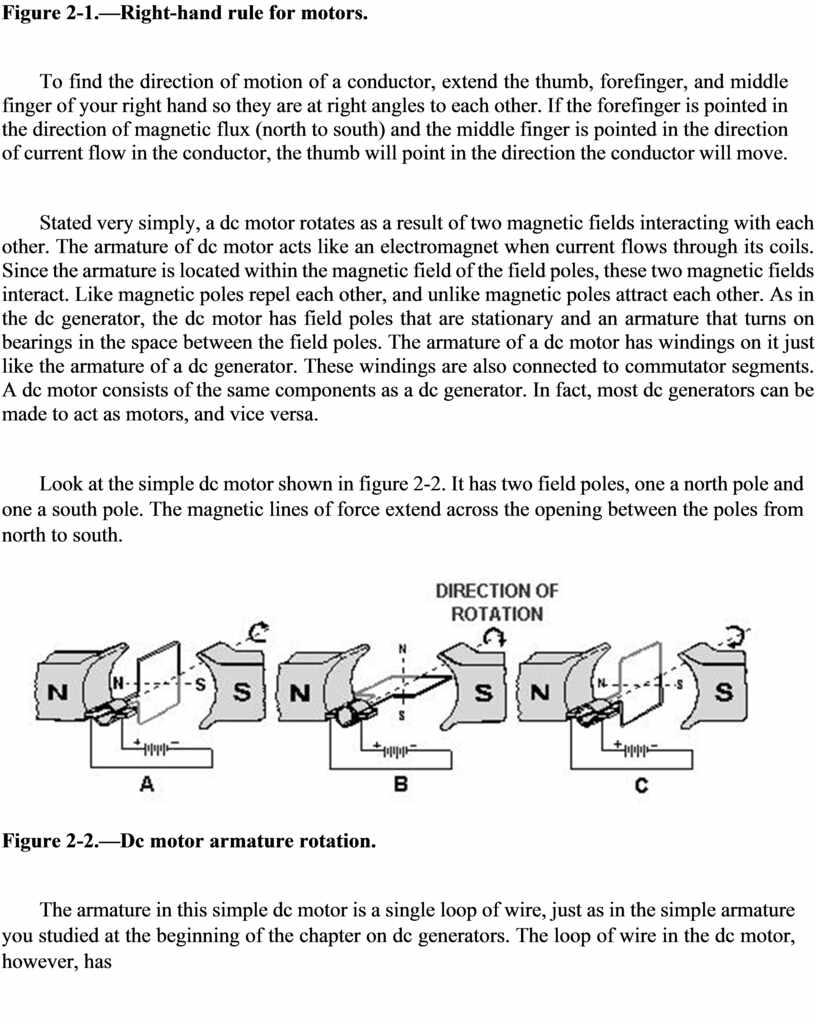
Look at the simple dc motor shown in figure 2-2. It has two field poles, one a north pole and one a south pole. The magnetic lines of force extend across the opening between the poles from north to south.
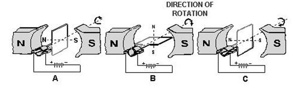
Figure 2-2.—Dc motor armature rotation.
The armature in this simple dc motor is a single loop of wire, just as in the simple armature you studied at the beginning of the chapter on dc generators. The loop of wire in the dc motor, however, has
current flowing through it from an external source. This current causes a magnetic field to be produced. This field is indicated by the dotted line through the loops. The loop (armature) field is both attracted and repelled by the field from the field poles. Since the current through the loop goes around in the direction of the arrows, the north pole of the armature is at the upper left, and the south pole of the armature is at the lower right, as shown in figure 2-2, (view A). Of course, as the loop (armature) turns, these magnetic poles turn with it. Now, as shown in the illustrations, the north armature pole is repelled from the north field pole and attracted to the right by the south field pole. Likewise, the south armature pole is repelled from the south field pole and is attracted to the left by the north field pole. This action causes the armature to turn in a clockwise direction, as shown in figure 2-2 (view B).
After the loop has turned far enough so that its north pole is exactly opposite the south field pole, the brushes advance to the next segments. This changes the direction of current flow through the armature loop. Also, it changes the polarity of the armature field, as shown in figure 2-2 (view C). The magnetic fields again repel and attract each other, and the armature continues to turn.
In this simple motor, the momentum of the rotating armature carries the armature past the position where the unlike poles are exactly lined up. However, if these fields are exactly lined up when the armature current is turned on, there is no momentum to start the armature moving. In this case, the motor would not rotate. It would be necessary to give a motor like this a spin to start it. This disadvantage does not exist when there are more turns on the armature, because there is more than one armature field. No two armature fields could be exactly aligned with the field from the field poles at the same time.
Instructions for demonstrations and safety
Warning: experiments with electricity should be performed under the supervision of teachers or adults familiar with electricity safety procedures.
Additional guidelines for organizing a lesson
1. Organization moment. Establishing emotional state. Checking for absent students.
2. Teacher introduces the topic and objectives of the lesson, assess criteria.
3. Teacher asks learners to divide into groups do Fill in the blank spaces exercise as a revision.
4. Students individually answer the qualitative questions of electric motors and explain briefly their working principle.
5. Students check their answers by using an answer sheet.
6. At the end of the lesson students are encouraged to reflect on what they have learned and
what they need to improve.
Recommendations for formative assessment
Activity1. Students discuss learning objectives and assess criteria.
Activity2. Learners are divided into groups and do Fill in the blank spaces exercise.
Activity3. Students individually answer the qualitative questions of electric motors and explain
briefly their working principle.
Activity4. Students check their answers by using an answer sheet.
Activity5. At the end of the lesson students are encouraged to reflect on what they have learned
and what they need to improve.
Answers, criteria for assignments, additional materials for the lesson
Activity2. Answer
1) coil of wire
2) rotate
3) stator
4) permanent
5) electromagnet
6) electrical
7) commutator
8) reverse direction
9) galvanometer
10) torque
11) radial
12) inter-acting
13) vibration
Longer Response Questions
1. (5 marks)
a) In a simple DC motor, describe the role of:
i) the commutator
ii) the stator
b) Explain what is meant by a “radial magnetic field”, and describe the advantage it gives in a
rotating-coil motor.
1.a) i) Commutator reverses the direction of current in the coil every 1/2 revolution. This is necessary to keep the torque in the same direction, and keep the coil turning. ii) The stator provides the magnetic field around the coil. It can be one or more permanent magnets or electro magnet .b) A “radial” field has its field lines in a pattern like the spokes of a wheel... radii of a circle. This means that the coil lies “flat” in the field (q=0o) through most rotation positions. Since the torque on the coil is proportional to Cos q, this ensures maximum torque throughout the rotation.
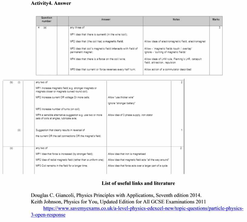
Activity4. Answer
List of useful links and literature
Douglas C. Giancoli, Physics Principles with Applications, Seventh edition 2014.
Keith Johnson, Physics for You, Updated Edition for All GCSE Examinations 2011
https://www.savemyexams.co.uk/a-level-physics-edexcel-new/topic-questions/particle-physics-
3-open-response
Скачано с www.znanio.ru
Материалы на данной страницы взяты из открытых источников либо размещены пользователем в соответствии с договором-офертой сайта. Вы можете сообщить о нарушении.