Поделиться

Discussion Point:
How many of the above concepts are recognisable in your experience of using a database?
In the relational database model each item of data is stored in a relation which is a special type of table. The strange choice of name has its origin in a mathematical theory. A relational database is a collection of relational tables.
When a table is created
in a relational database it is first given a name and then the attributes are
named. In a database design, a table would be given a name with the attribute
names ![]() isted in brackets after the table name. For example, a database for the
theatrical agency may contain the following tab es:
isted in brackets after the table name. For example, a database for the
theatrical agency may contain the following tab es:
Member(MemberlD, MemberGivenName, MemberFamilyName, BandName, ...)
Band(BandName, AgentID, ...)
|
113 |
|
MemberlD |
Member GivenName |
Member FamilyName |
Band Name |
|
|
0005 |
Xiangfei |
Jha |
ComputerKidz |
|
|
0009 |
Mahesh |
Ravuru |
ITWizz |
|
|
0001 |
Dylan |
Stoddart |
ComputerKidz |
|
|
0025 |
Vandana |
Graham |
ITWizz |
|
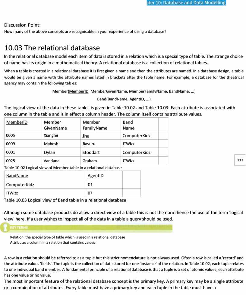
Table 10.02 Logical view of Member table in a relational database
|
BandName |
AgentID |
|
|
ComputerKidz |
01 |
|
|
ITWizz |
07 |
|
Table 10.03 Logical view of Band table in a relational database
Although some database products do allow a direct view of a table this is not the norm hence the use of the term 'logical view' here. If a user wishes to inspect all of the data in a table a query should be used.
![]()
Relation: the special type of table which is used in a relational database
Attribute: a column in a relation that contains values
A row in a relation should be referred to as a tuple but this strict nomenclature is not always used. Often a row is called a 'record' and the attribute values 'fields'. The tuple is the collection of data stored for one 'instance' of the relation. In Table 10.02, each tuple relates to one individual band member. A fundamental principle of a relational database is that a tuple is a set of atomic values; each attribute has one value or no value.
The most important feature of the relational database concept is the primary key. A primary key may be a single attribute or a combination of attributes. Every table must have a primary key and each tuple in the table must have a value for the primary key and that value must be unique. Once a table and its attributes have been defined the next task is to choose the primary key. In some cases there may be more than one attribute for which unique values are guaranteed. In this case, each one is a candidate key and one will be selected as the primary key. More often there is no candidate key and so a primary key has to be created. Table 10.02 shows an example of this with the introduction of the attribute MemberID as the primary key (the primary key is underlined in the logical v•ew).
The primary key ensures 'entity integrity'. The DBMS will not allow an attempt to insert a value for a primary key when that value already exists. Therefore each tup e must be unique. This is one of the features of the relational model that helps to ensure data integrity. The primary key also provides a unique reference to any attribute value that a query is selecting.
Although it is possible for a database to contain stand-alone tables it is usually true that each table will have some relationship with another table. This relationshÞ is implemented by using a foreign key.
Primary key: an attribute or a combination of attributes for which there is a value in each tuple and that value is unique
Foreign key: an attribute in one table that refers to the primary key in another table
![]()
![]() The use of a foreign key
can be discussed on the basis of the two database tables represented in Table
10.02 and Table 10.03. When the database is being created, the Band table is
created first. BandName is chosen as the primary key because unique names for bands
can be guaranteed. Then the Member table is created. MemberlD is defined as the
primary key and the attribute BandName is identified as a foreign key
referencing the primary key in the Band table. Once this relationship between
primary and foreign keys has been established, the DBMS will prevent any entry
for BandName in the Member table being made if the corresponding value does not
exist in the Band table. This provides referential integrity which is another
reason why the relational database model helps to ensure data integrity.
The use of a foreign key
can be discussed on the basis of the two database tables represented in Table
10.02 and Table 10.03. When the database is being created, the Band table is
created first. BandName is chosen as the primary key because unique names for bands
can be guaranteed. Then the Member table is created. MemberlD is defined as the
primary key and the attribute BandName is identified as a foreign key
referencing the primary key in the Band table. Once this relationship between
primary and foreign keys has been established, the DBMS will prevent any entry
for BandName in the Member table being made if the corresponding value does not
exist in the Band table. This provides referential integrity which is another
reason why the relational database model helps to ensure data integrity.
BandName is a primary key for the Band table. Does this mean that as a foreign key in the Member table it must have unique values? Explain your reasoning.
The top-down, stepwise refinement
(see Chapter 12, Section 12.01) approach to database design uses an
entity-relationship (ER) diagram. This might be initially created and used by a
systems analyst before being passed on to the database designer. Otherwise the
designer has to create •t. The term 'relationship' (not to be confused with a
relation) was introduced earlier in connection with the use of a foreign key.
An entity (strictly speaking an entity ![]() type) could be a thing, a type of person, an event, a
transaction or an organisation. Most importantly, there must be a number of
'instances' of the entity. An entity is something that will become a table in a
relational database.
type) could be a thing, a type of person, an event, a
transaction or an organisation. Most importantly, there must be a number of
'instances' of the entity. An entity is something that will become a table in a
relational database.
|
WORKED EXAMPLE 10.01 |
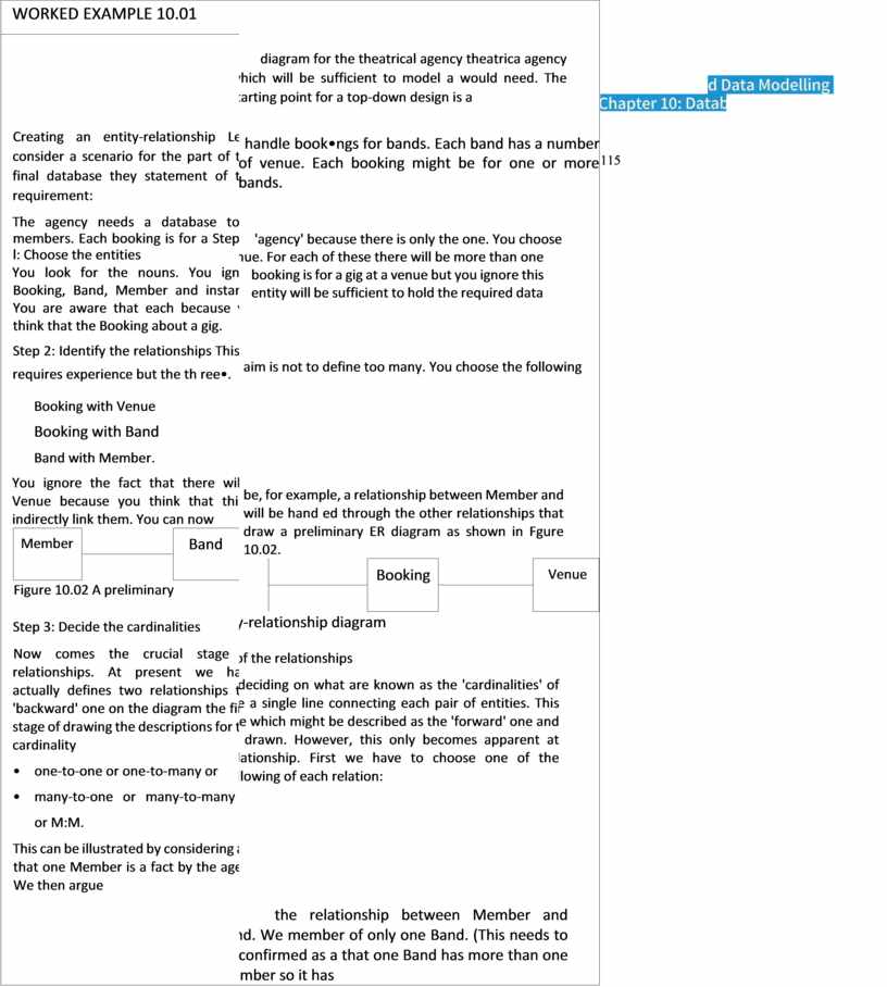
diagram for the theatrical agency theatrica agency which will be sufficient to model a would need. The starting point for a top-down design is a handle book•ngs for bands. Each band has a number of venue. Each booking might be for one or more bands. 'agency' because there is only the one. You choose Venue. For each of these there will be more than one booking is for a gig at a venue but you ignore this entity will be sufficient to hold the required data aim is not to define too many. You choose the following be, for example, a relationship between Member and will be hand ed through the other relationships that draw a preliminary ER diagram as shown in Fgure 10.02.
entity-relationship diagram of the relationships deciding on what are known as the 'cardinalities' of the a single line connecting each pair of entities. This line which might be described as the 'forward' one and as drawn. However, this only becomes apparent at relationship. First we have to choose one of the following of each relation: the relationship between Member and Band. We member of only one Band. (This needs to be confirmed as a that one Band has more than one Member so it has |
||||||
|
Creating an entity-relationship Let's consider a scenario for the part of the final database they statement of the requirement: The agency needs a database to members. Each booking is for a Step l: Choose the entities You look for the nouns. You ignore Booking, Band, Member and instance. You are aware that each because you think that the Booking about a gig. Step 2: Identify the relationships This requires experience but the th ree•. Booking with Venue Booking with Band Band with Member. You ignore the fact that there will Venue because you think that this indirectly link them. You can now
Figure 10.02 A preliminary Step 3: Decide the cardinalities Now comes the crucial stage of relationships. At present we have actually defines two relationships the 'backward' one on the diagram the final stage of drawing the descriptions for the cardinality • one-to-one or one-to-many or • many-to-one or many-to-many or M:M. This can be illustrated by considering argue that one Member is a fact by the agency.) We then argue |
|
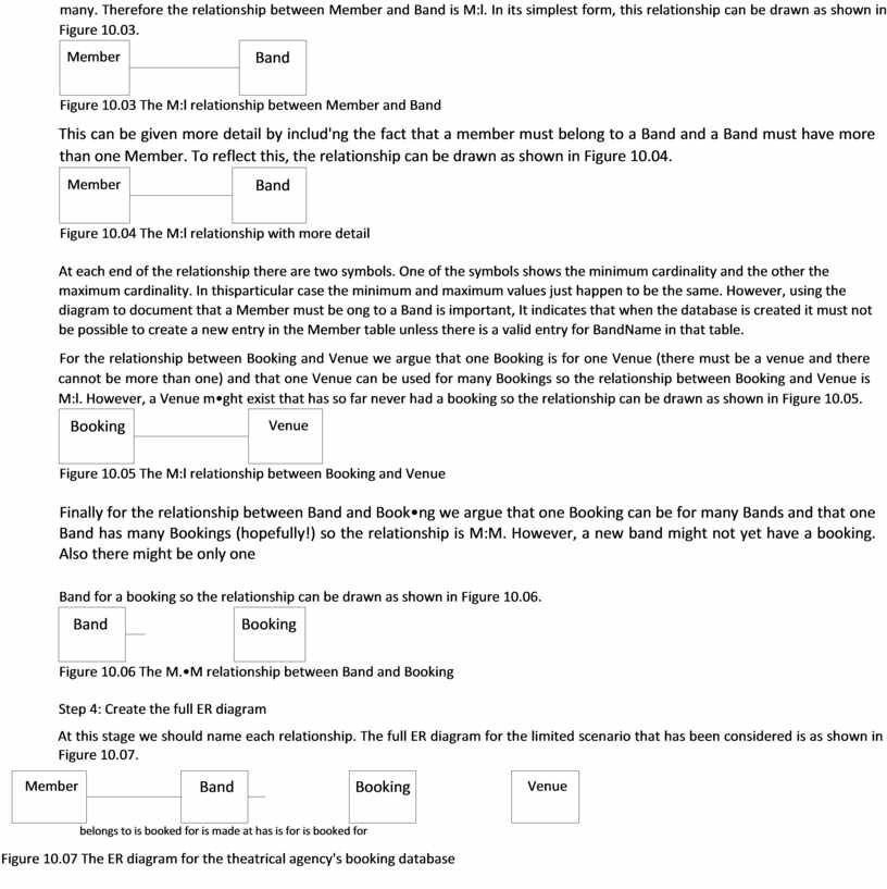
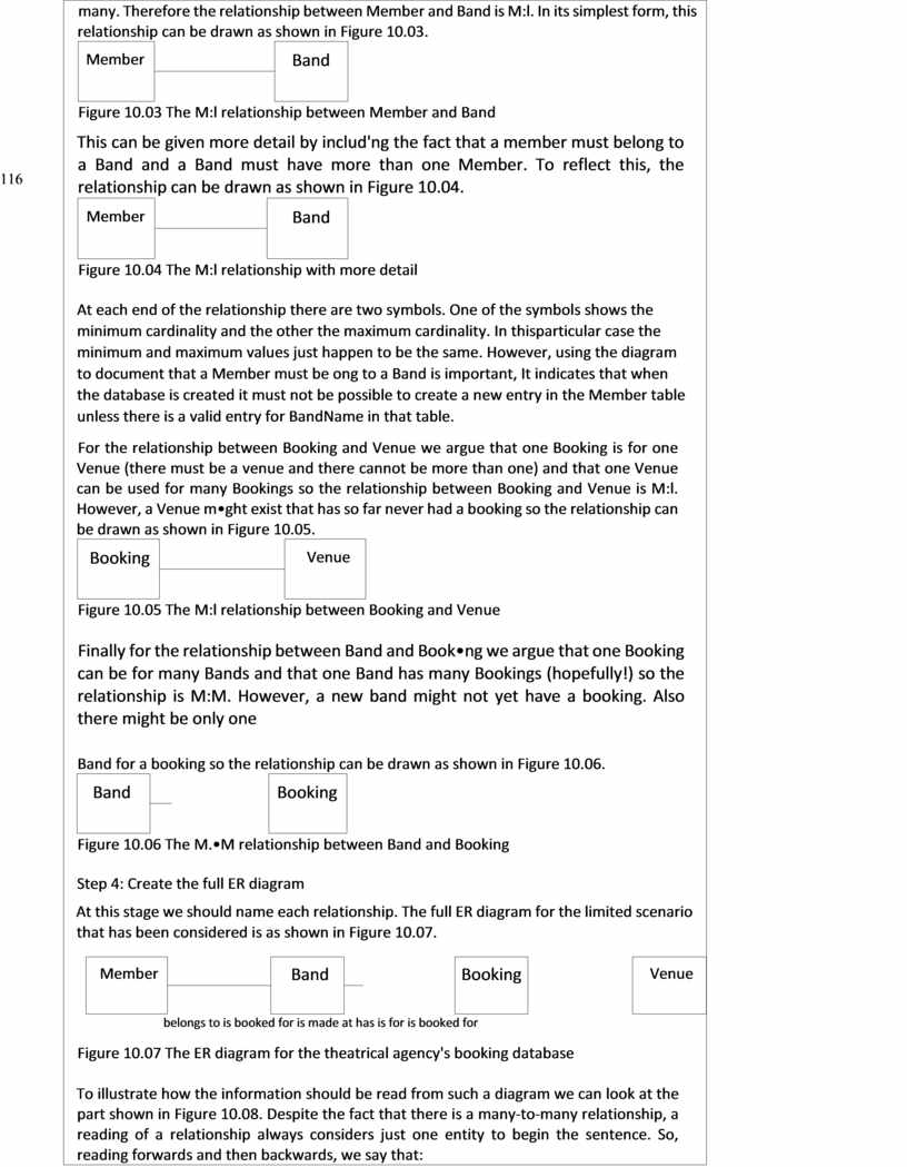
many. Therefore the relationship between Member and Band is M:l. In its simplest form, this relationship can be drawn as shown in Figure 10.03.
Figure 10.03 The M:l relationship between Member and Band This can be given more detail by includ'ng the fact that a member must belong to a Band and a Band must have more than one Member. To reflect this, the relationship can be drawn as shown in Figure 10.04.
Figure 10.04 The M:l relationship with more detail At each end of the relationship there are two symbols. One of the symbols shows the minimum cardinality and the other the maximum cardinality. In thisparticular case the minimum and maximum values just happen to be the same. However, using the diagram to document that a Member must be ong to a Band is important, It indicates that when the database is created it must not be possible to create a new entry in the Member table unless there is a valid entry for BandName in that table. For the relationship between Booking and Venue we argue that one Booking is for one Venue (there must be a venue and there cannot be more than one) and that one Venue can be used for many Bookings so the relationship between Booking and Venue is M:l. However, a Venue m•ght exist that has so far never had a booking so the relationship can be drawn as shown in Figure 10.05.
Figure 10.05 The M:l relationship between Booking and Venue Finally for the relationship between Band and Book•ng we argue that one Booking can be for many Bands and that one Band has many Bookings (hopefully!) so the relationship is M:M. However, a new band might not yet have a booking. Also there might be only one
Band for a booking so the relationship can be drawn as shown in Figure 10.06.
Figure 10.06 The M.•M relationship between Band and Booking Step 4: Create the full ER diagram At this stage we should name each relationship. The full ER diagram for the limited scenario that has been considered is as shown in Figure 10.07.
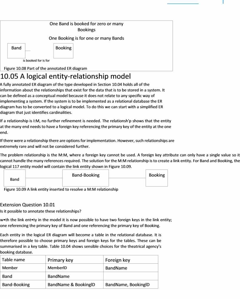
belongs to is booked for is made at has is for is booked for Figure 10.07 The ER diagram for the theatrical agency's booking database To illustrate how the information should be read from such a diagram we can look at the part shown in Figure 10.08. Despite the fact that there is a many-to-many relationship, a reading of a relationship always considers just one entity to begin the sentence. So, reading forwards and then backwards, we say that: |
116
|
One Band is booked for zero or many Bookings One Booking is for one or many Bands
is booked for is for Figure 10.08 Part of the annotated ER diagram |
A fully annotated ER diagram of the type developed in Section 10.04 holds all of the information about the relationships that exist for the data that is to be stored in a system. It can be defined as a conceptual model because it does not relate to any specific way of implementing a system. If the system is to be implemented as a relational database the ER diagram has to be converted to a logical model. To do this we can start with a simplified ER diagram that just identifies cardinalities.
If a relationship is I:M, no further refinement is needed. The relationsh'p shows that the entity at the many end needs to have a foreign key referencing the primary key of the entity at the one end.
If there were a relationship there are options for implementation. However, such relationships are extremely rare and will not be considered further.
The problem relationship is the M:M, where a foreign key cannot be used. A foreign key attribute can only have a single value so it cannot handle the many references required. The solution for the M:M relationship is to create a link entity. For Band and Booking, the logical 117 entity model will contain the link entity shown in Figure 10.09.
|
Band |
|
Band-Booking |
|
Booking |
|
|
|
Is it possible to annotate these relationships?
w•th the link
ent•ty in the model it is now possible to have two foreign keys in the link
entity; ![]() one referencing the primary key of Band and one referencing the primary
key of Booking.
one referencing the primary key of Band and one referencing the primary
key of Booking.
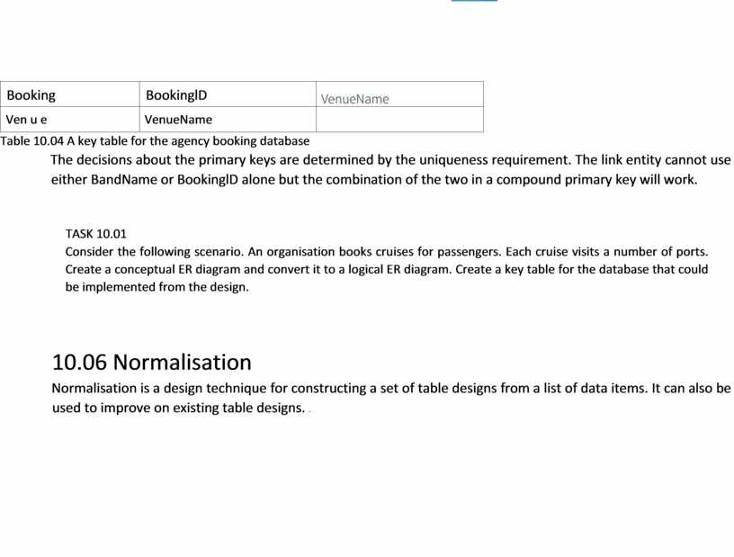
Each entity in the logical ER diagram will become a table in the relational database. It is therefore possible to choose primary keys and foreign keys for the tables. These can be summarised in a key table. Table 10.04 shows sensible choices for the theatrical agency's booking database.
|
Table name |
Primary key |
Foreign key |
|
Member |
MemberlD |
BandName |
|
Band |
BandName |
|
|
Band-Booking |
BandName & BookinglD |
BandName, BookinglD |
|
Booking |
BookinglD |
|
|
Ven u e |
VenueName |
|
Table 10.04 A key table for the agency booking database
The decisions about the primary keys are determined by the uniqueness requirement. The link entity cannot use either BandName or BookinglD alone but the combination of the two in a compound primary key will work.
TASK 10.01
Consider the following scenario. An organisation books cruises for passengers. Each cruise visits a number of ports. Create a conceptual ER diagram and convert it to a logical ER diagram. Create a key table for the database that could be implemented from the design.
Normalisation is a design technique for
constructing a set of table designs from a list of data items. It can also be
used to improve on existing table designs. ![]()
|
|
|
118
Материалы на данной страницы взяты из открытых источников либо размещены пользователем в соответствии с договором-офертой сайта. Вы можете сообщить о нарушении.